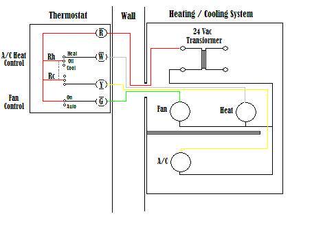
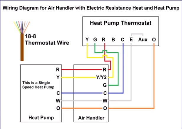
The o terminal in this diagram is for use for a heat pump thermostat installation for the reversing valve. Finally the illustration below is for a system with a single transformer.
Wiring A Thermostat Home Automation Tech
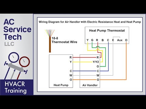
Heat pump thermostat wiring diagram. This way you have a reference. The basic heat pump wiring for a heat pump thermostat is illustrated here. A heat pump thermostat will use the orange wire for the reversing valve in the condenser. This diagram shows what each terminal designation that goes to the hvac system. It shows the components of the circuit as simplified shapes and the power and signal contacts amid the devices. These two connections will ensure that there is power to the thermostat that you are operating.
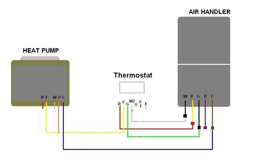
As shown in the diagram you will need to power up the thermostat and the 24v ac power is connected to the r and c terminals. Heat pump thermostat wiring a typical wire color and terminal diagram. Before uninstalling the old thermostat take a picture of the wiring with your cell phone before removing the wires. Ac heat pump with standard air handler and single stage electric backup heat standard heat pump thermostat heat pump condenser 24 volt fan only operation common air conditioning heat pump reversing valve electric backup heat low voltage connection some ac systems will have a blue wire with a pink stripe in place of the yellow or y wire. C is known as the common terminal. Nest thermostat wiring diagram heat pump wiring diagram is a simplified up to standard pictorial representation of an electrical circuit.
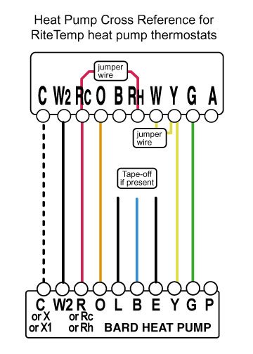
Heat pump thermostat wiring chart diagram. It corresponds to the chart below to explain the thermostat terminal functions. The color of wire r is usually red and c is black.
Gallery of Heat Pump Thermostat Wiring Diagram