Notice that wires come out of the device through two protuberances. A very first appearance at a circuit diagram could be confusing however if you could review a subway map you can check out schematics.
Ballast Gard High Pressure Sodium Starter Cutout Switch If
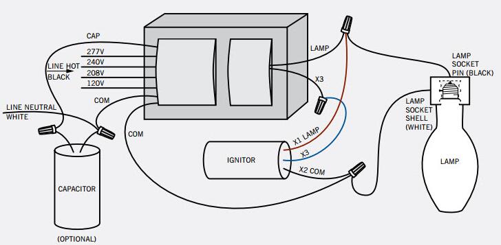
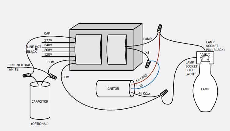
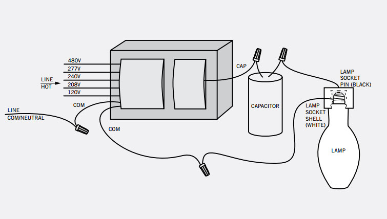
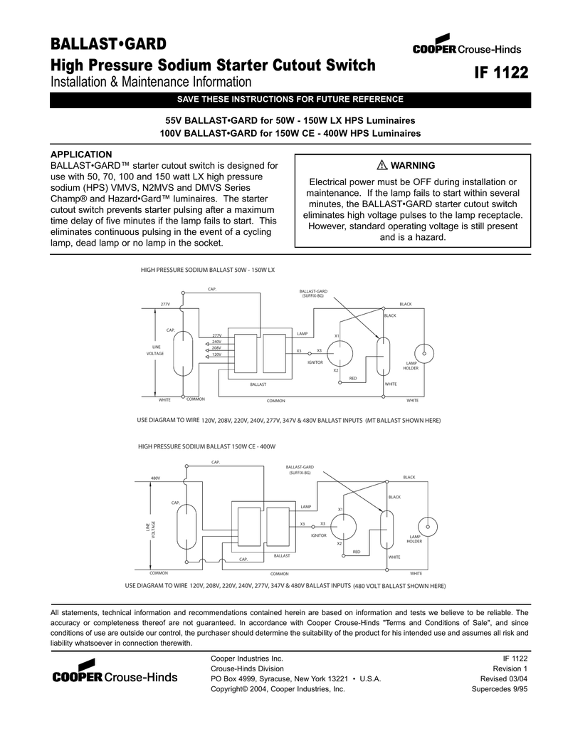
Hps ballast wiring diagram. The ballast data tables in our catalog indicate the page number and reference letter corresponding to the correct diagram for each ballast product. Hps ballasts brackets wiring diagrams warranty information. High pressure sodium ballast wiring diagram a beginner s overview of circuit diagrams. 5 150 250w mh 480v 6 250 1000w hps 480v electronic ballast wiring diagrams 1 t5 2 lamp 2 t5 4 lamp 7 pulse start mh 9 5 tap hps 8 5 tap mh 4 t8 3 lamp 240v 277v com com 120v 208v 480v cap lamp ignitor tap x3 x2 x1 277v black 240 tan 208 purple 120v orange white common blk wht blk whtred blue cap red ignitor lamp yellow 5 t8. February 2 2019 by larry a. The wiring diagram shows three components connected to the lamp the transformer the capacitor and the ignitor.
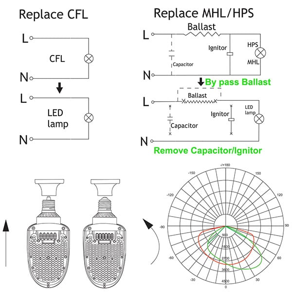
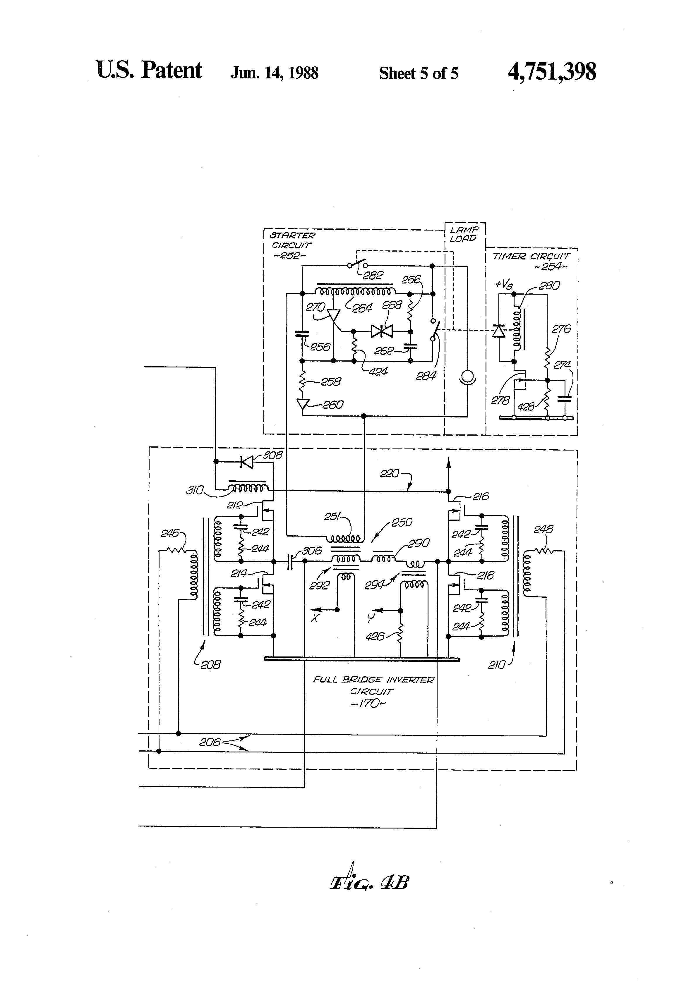
It reveals the parts of the circuit as streamlined forms and the power and signal links between the gadgets. The wiring diagram is the blueprint for the ballast circuitry including the input supply voltage and grounding methods. Wellborn collection of high pressure sodium ballast wiring diagram. Inspect the two sides on the transformer to see its long side and the short side. Wiring diagrams for venture hps and remote ballast products are provided on this page. A ground connection must be made to all ballasts to avoid shock hazard personal injury or damage to the luminaire or installationsolved.
A wiring diagram is a simplified standard photographic depiction of an electric circuit. The capacitor has two wires and the ignitor has three wires x1 x2 and x3.
Gallery of Hps Ballast Wiring Diagram