Reapply power check operation. It shows the components of the circuit as simplified shapes and also the power and also signal links between the devices.
Ot Do We Have An Electronics Wiz In The House Ourfigs Com
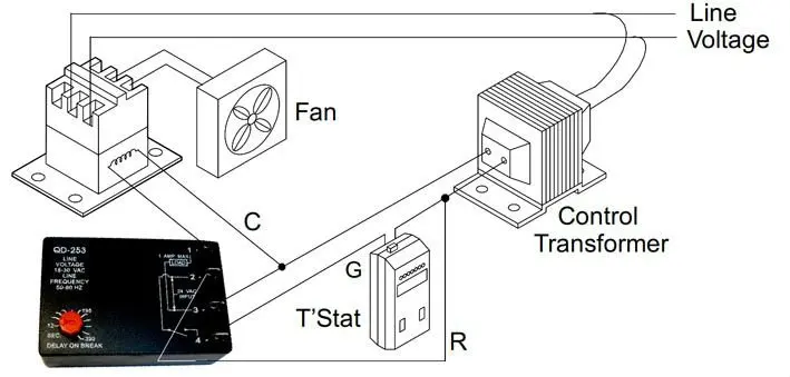
Icm253 wiring diagram. Select desired delay on make and delay on break periods. Upon closure of the initiate switch the delay on. 1 and 4 bypass undo and reconnect the current green wire from the fan 1 and the green wire from the thermostat 4 2 and 3 tap add into existing into the 24vac from the red 2 and bluecommonneutral 3 wires. 3152335276 application assistance 8003655525 7313 william barry blvd north syracuse ny 13212 our products are proudly manufactured in the usa. A wiring diagram is a simplified traditional pictorial representation of an electrical circuit. Reapply power check operation.
Had an old 30 second delay on break timer that went bad hvac guy that used to do my work just pulled it out and hooked it up direct. Hvac in romnä. The time delay begins when the initiate contact. Collection of icm254 wiring diagram. Cat master bu catalog. If it does not work below is an explanation.
When the initiate contact closes the load energizes and remains energized as long as the initiate contact is closed. So now when thermostat kicks outside unit on the fan and compressor come on at the same time and shut down at the same time. Cat master bu catalog. Mode of operation power must be applied before and during the time delay period. A wiring diagram is a type of schematic which uses abstract pictorial icons to reveal all the interconnections of parts in a system. Icm254 wiring diagram just whats wiring diagram.
Icm controls icm253 icm253 fan blower control off delay on break 12 390 second adjustable delay controls the circulating fan in heat pump air conditioning and forced air systems. When the initiate contact closes the load energizes and remains energized as long as the initiate contact is closed. Wiring diagram replaces thermal time delays off delay purges ducts of residual air to increase efficiency power must be applied before and during the time delay period. Select desired delay on break period. Like the diagram on the icm253 unit. Icons that represent the parts in the circuit as well as lines that represent the connections between them.
On delay lets air reach proper level prior to energizing fan off delay purges ducts of residual air to increase efficiency mode of operation power must be applied at all times. Wiring diagrams are made up of two things. Icm254 wiring diagram download icm253 wiring diagram sportsbettor. Going to try and post a pic of what i have got.
Gallery of Icm253 Wiring Diagram