1120002170 ic m5223fp ic a200 main unit 5 pieces 8810006840 screw fh m264 ic a200 top cover 10 pieces addresses are provided on the inside back cover for your convenience. Never connect the transceiver to an ac outlet or to a dc power supply that uses more than 16 v.

5480 Icom Ic A200 Service Manuals Guide Wiring Library
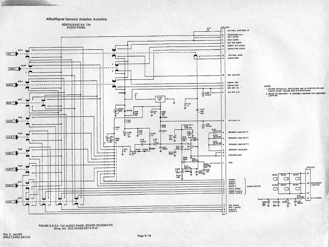
Icom ic a200 wiring diagram. Rear view 5 13 14 25 1 15 4 circuit breaker 10 a 138 v dc or 275 v dc power ground circuit breaker to prevent physical damage a 10 a circuit breaker must be installed in the dc power line in the aircraft. Spa 4s icom a 200 a 210 radio installation wiring diagram 10 5 2015 spa 4sicoma 200instpdf notes 1. Icom ic a200 installation instructions manual vhf air band transceiver hide thumbs. This will ruin the transceiver. Icom a200 wiring diagram wiring diagram is a simplified conventional pictorial representation of an electrical circuit. It shows the components of the circuit as simplified shapes and the knack and signal associates in the company of the devices.
If pilot ptt switch is connected to the aircraft hand mic jack it must be disconnected and con nected to the white red wire as shown. D power cable wiring use two pairs of 20 awg wire for the power and power grounding connections. See radio manufacturers installation instruc.
Gallery of Icom Ic A200 Wiring Diagram