Schematic wiring diagram for dc electric motor connections. Smart light switch wiring diagrams.

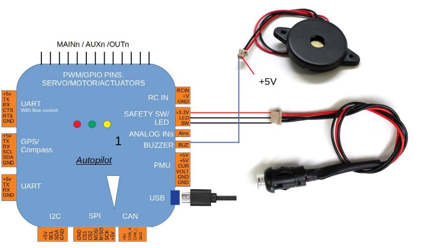
Inertial Navigation System Wikipedia
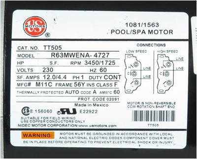
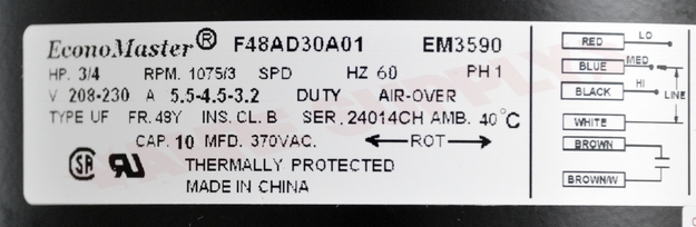
Ins on motor wiring diagram. Ins on motor wiring diagram. Single phase motor wiring diagram with capacitor baldor single phase motor wiring diagram with capacitor single phase fan motor wiring diagram with capacitor single phase motor connection diagram with capacitor every electrical arrangement is made up of various unique pieces. Each component ought to be placed and linked to different parts in particular manner. Active 1 year 2 months ago. Viewed 1k times 1 begingroup im trying to connect a 220 single phase motor the wiring diagram is on a sticker on the motor. Related articles more from author.
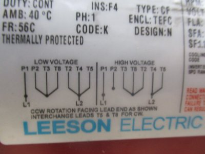
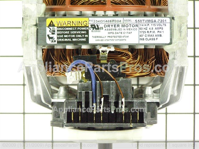
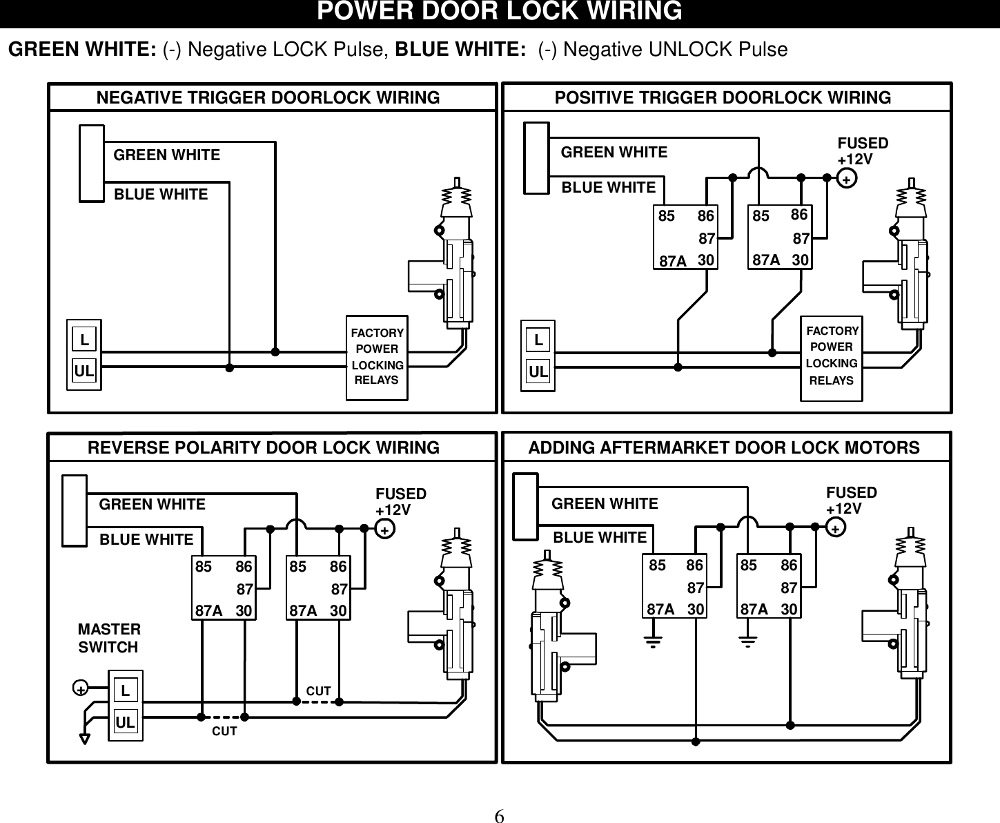
However im not sure what the brown wire is supposed to be connected to i think it says ins which im. Inst maint wiringqxd 5032008 1002 am page 6. All you have to do is a open the connection box of the motor look for the two wires of the starting or running coil inverse only one coil wire. Switched outlet wiring diagrams. On my emerson electric 1hp motor the wiring diagram uses the term ins l1 l2. The usual aspects in a wiring diagram are ground power supply wire as well as link result gadgets switches resistors reasoning gateway lights etc.
To check out a wiring diagram initially you have to know just what fundamental elements are consisted of in a wiring diagram as well as which pictorial icons are made use of to represent them. Ask question asked 1 year 2 months ago. Other wiring diagrams can be found here. These diagrams are current at the time of publication check the wiring diagram supplied with the motor. What wire red black goes where. Answered by a verified electrician.
Refer to the motor manufacturers data on the motor for wiring diagrams on standard frame ex e ex d etc.
Gallery of Ins On Motor Wiring Diagram