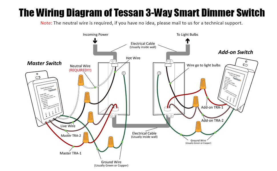
Light switch wiring diagram single pole this light switch wiring diagram page will help you to master one of the most basic do it yourself projects around your house. Introduction installation guide installing remote switches.

Fiber To The X Wikipedia
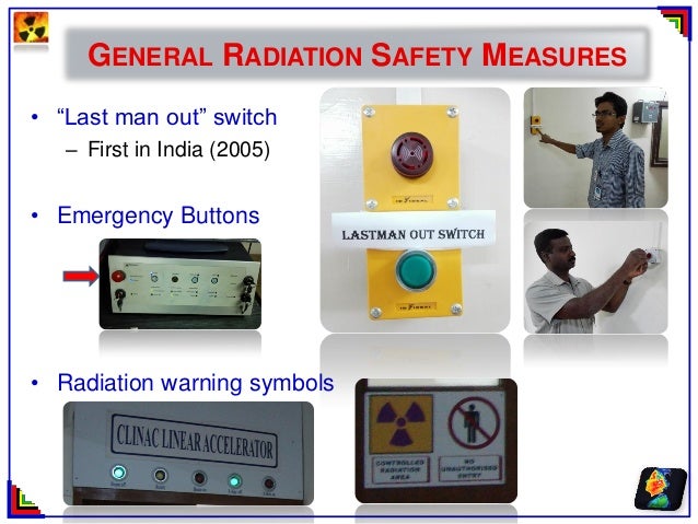
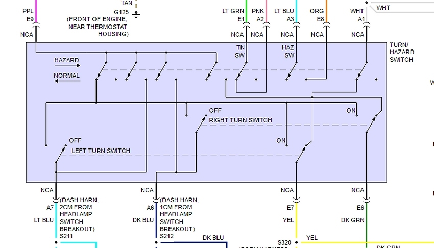
Last man out switch wiring diagram. Switch types 11 using the remote switch inputs 12 to set up a scene 15 to set led colours 16 to restore default led colours 16 to restore default thescene settings 16 holiday mode 17 troubleshooting 19 specification 20. The black wire power in source attaches to one of the switch screw terminals. Three wire cable runs between the switches and the outlet. Switch wiring shows the power source power in starts at the switch box. Last man out function not sure if the upstairs lights are still on. The black wire power out wiring attaches to the other switch screw terminal.
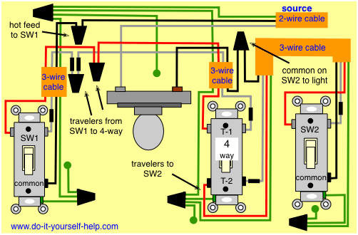
In this diagram two 3 way switches control a wall receptacle outlet that may be used to control a lamp from two entrances to a room. This circuit is wired the same way as the 3 way lights at this link. 3 way switched outlet wiring. The source is at the sw1 where the hot is connected to. Whether you have power coming in through the switch or from the lights these switch wiring diagrams will show you the light. Circuit electrical wiring enters the switch box.
Explanation of wiring diagram 1. He doesnt want individual switches so im proposing fitting 1 switch and a contactor at the end of the day he throws the 1 switch and the contactor switches off the lights. Im looking at installing a last man switch basically the customer switches off his lights at the distribution board in the office electrical cupboard. Fixture wiring exits the switch box. Easily remedied by a master switch inside the front door to turn everything off when you leave and back on when you return 751 325 providing switching for external power so that sockets on the outside of buildings are only powered when you want to use them.
Gallery of Last Man Out Switch Wiring Diagram