Field wiring for both communicating and non communicating applications is illustrated in diagrams which begin on page 13. In all cases setup is critical to ensure proper system operation.
Furnace Wiring Schematic Wiring Diagram
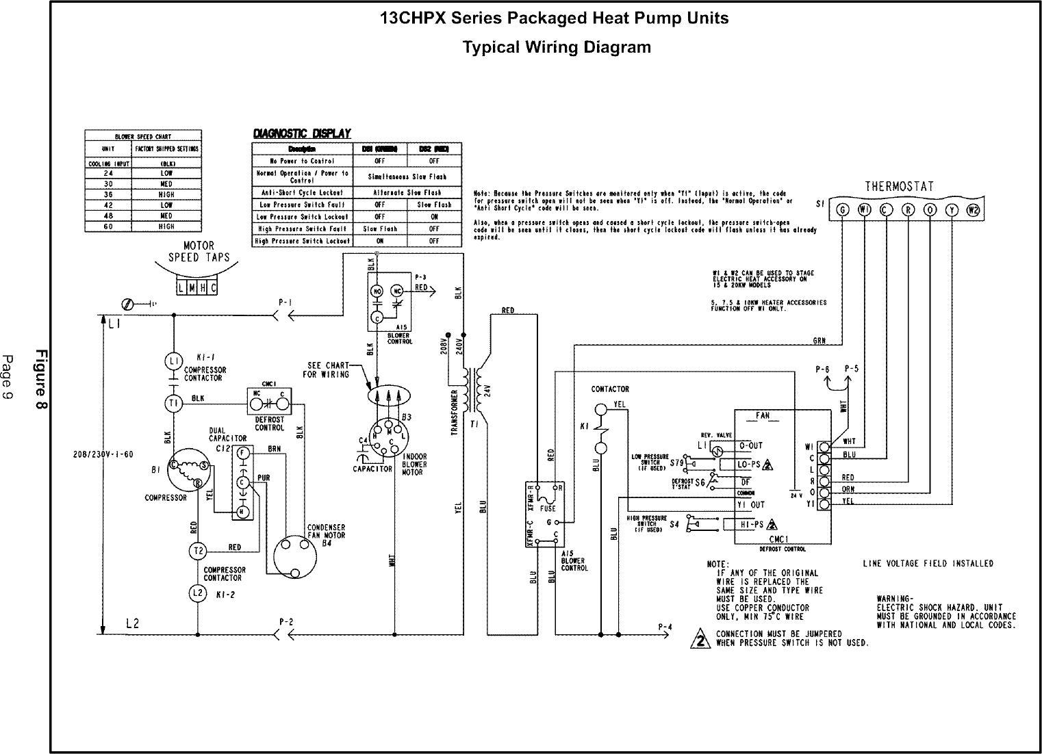
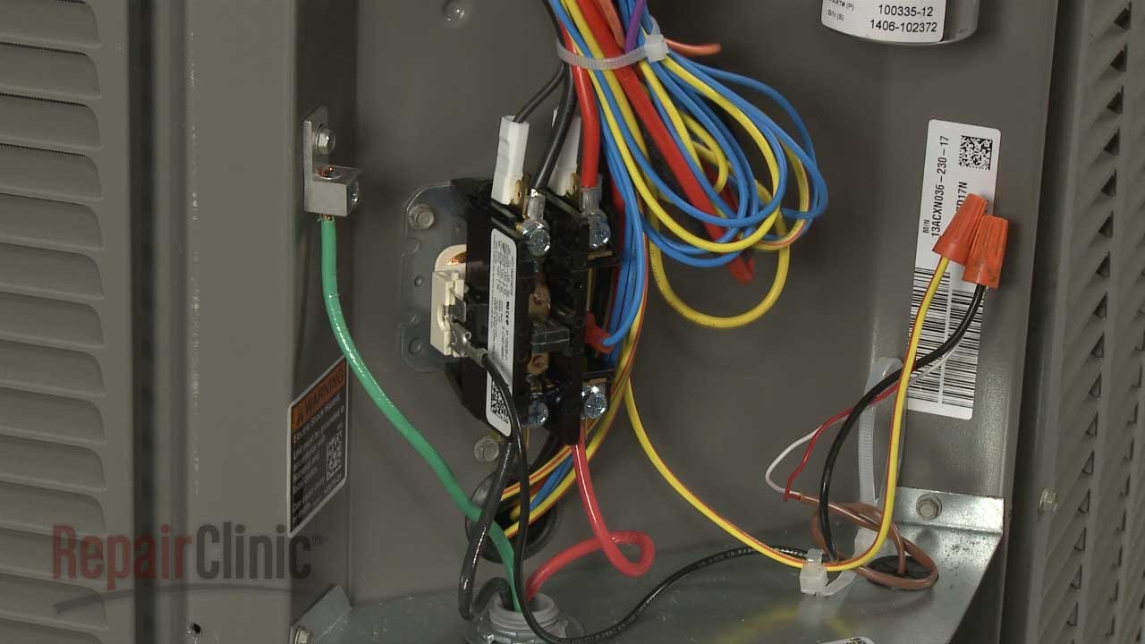
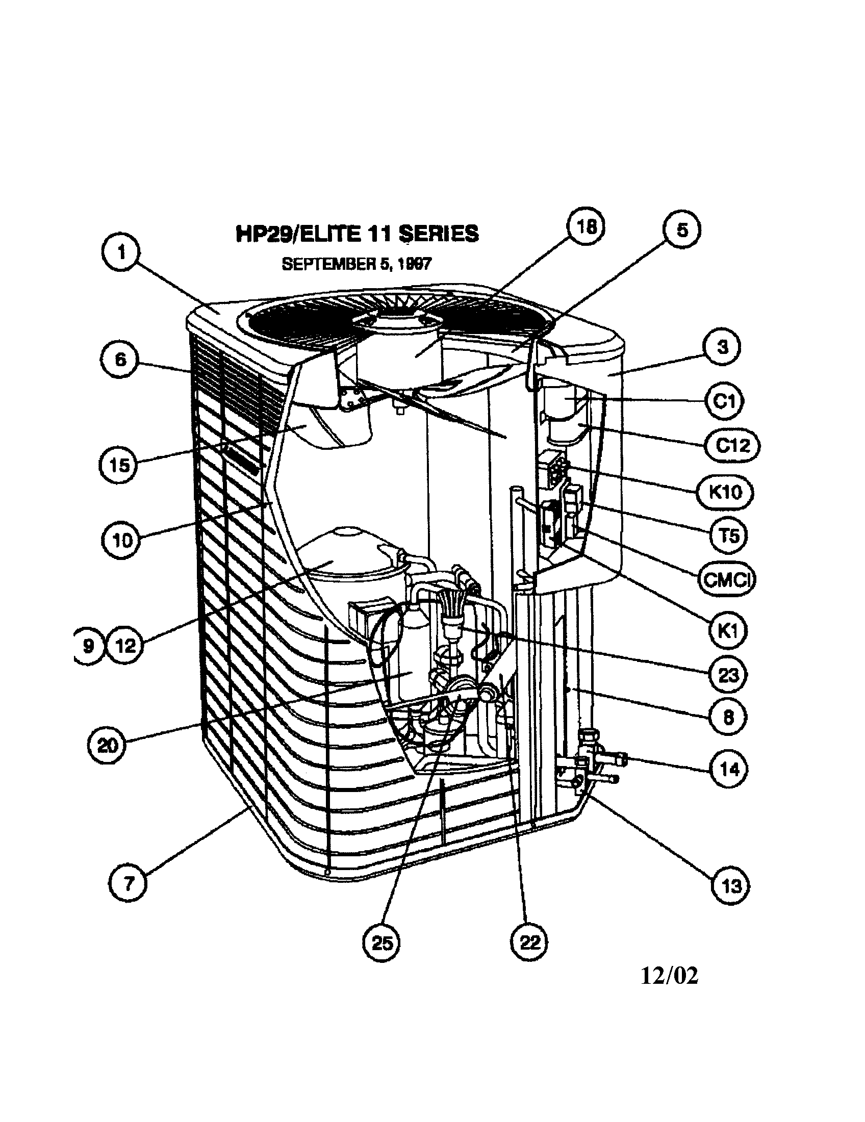
Lennox wiring diagram. Improper installation adjustment alteration service or maintenance can cause property damage or personal injury. It has a two speed compressor that someone in the past has pulled and taped off the coil wire on one of the two compressor contactors. It shows the components of the circuit as simplified forms and also the power and also signal connections between the devices. Lennox ventilation control system lvcs indoor coilair handler kits. My church has an old lennox hp17 953 heat pump split system that the wiring diagram is missing from. Connect optional purchase separately outdoor sensor.
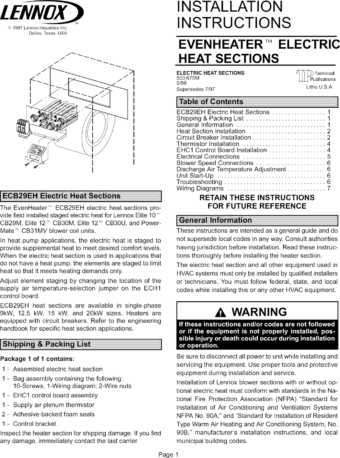
Find your owners literature like product manuals by searching your products model number. Connect wiring between thermostat indoor unit and outdoor unit as shown in the appropriate wiring diagram. Collection of lennox wiring diagram. See installing outdoor sensor for further details and provided wiring diagrams. Wall mounting instructions a. Note due to lennox ongoing committment to quality specifications ratings and dimensions subject to change without notice and without incurring liability.
Seal the hole in the wall with a suitable material to prevent drafts from entering the. 4 inch filter rack kit ela 072 240 air handler units. Connect wiring between thermostat indoor unit and outdoor unit and other de vices as shown in the wiring diagrams figures 5. A wiring diagram is a streamlined traditional photographic depiction of an electrical circuit. Find lennox commercial hvac product service manuals installation guides engineering handbooks application and design guidelines. When i reconnect the coil wire it runs for about 30 seconds before something trips it off.
Lennox wiring diagram building electrical wiring representations reveal the approximate places and also affiliations of receptacles lighting and permanent electric services in a structure. Interconnecting cord paths may be revealed roughly where specific receptacles or fixtures need to be on a typical circuit. Use a level to align the thermostat baseplate against the wall where the thermo stat will be installed see figure 1. Looking for more information about your lennox product. A wiring diagram would be great but of course it is long gone. T3eh fuse block replacement kit 102763 01 taa drip shield kit 73w88 taa heat pump check valve kit 47w48 and 50w73 taa return air grille 47w49 47w50.
In noncommunicating applications the lennox comfortsense 7000 thermostat may be used as well as other noncommunicating thermostats. 5 inch merv 11 and 16 filter rack kit taa air handlers. Mark an appropriate hole location on the wall.
Gallery of Lennox Wiring Diagram