Hold the level switch in the off position. The lcm can also be installed inside the internal control panel inside each lift.
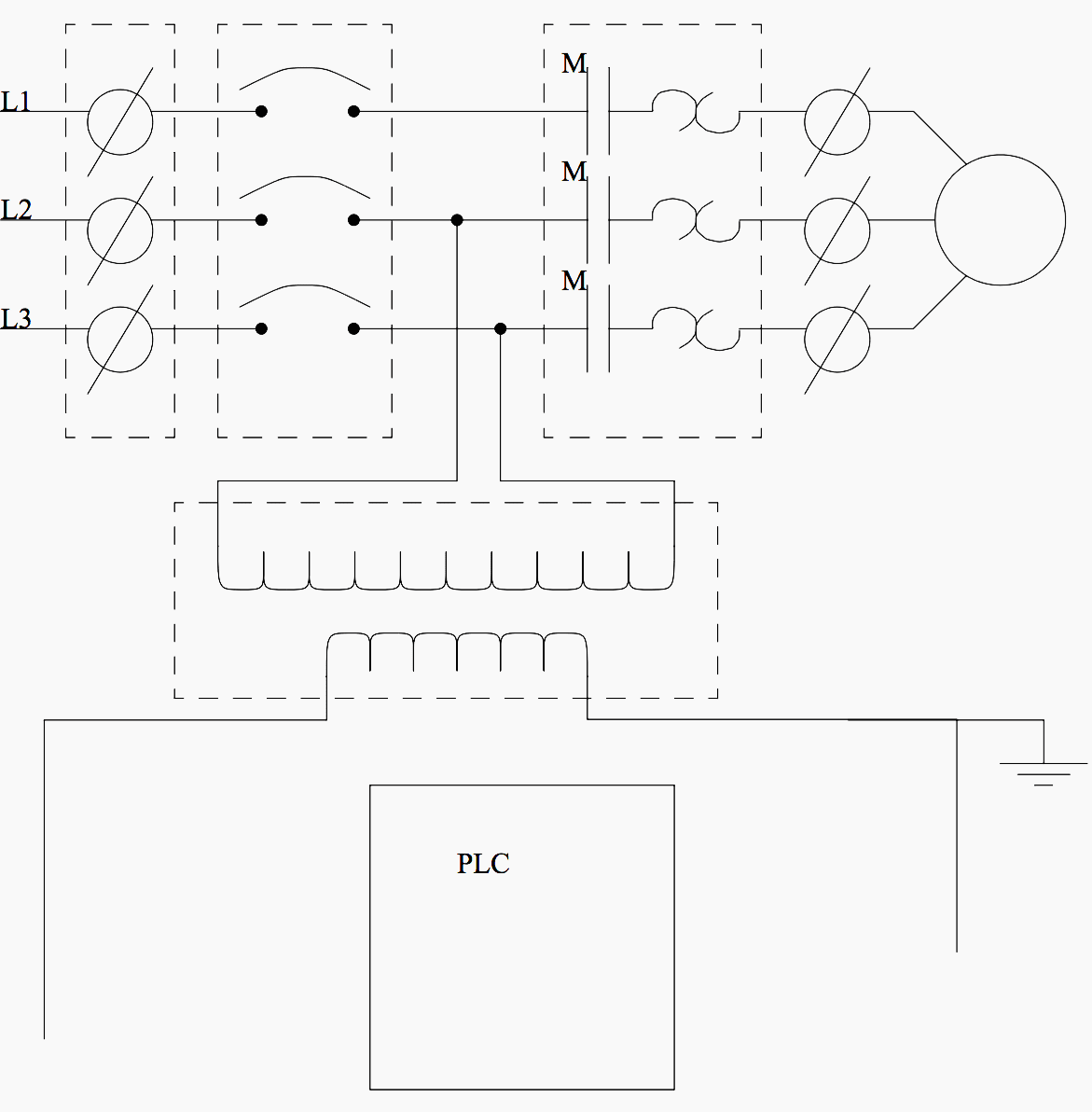
Basic Electrical Design Of A Plc Panel Wiring Diagrams Eep
Lift control panel wiring diagram pdf. Do not let go of the level switch until the lift has stopped. Turn off the unit when not in use. This will turn off power to motor 2. The lift control module lcm is generally installed on top of the roof of the lift cart in close proximity to the rest of the lift systems electrical hardware. Diagnostics diagnostics sbc opn cls stp com eye only eye eye edge com 1 2 3 open close to main board power. This facilitates easy access to wire each control lift button.
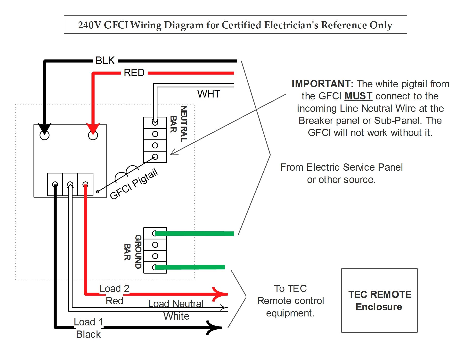
Control box wiring guide for normally closed limits g8 units made after february 262018. 3 access control reader acr dimensions. Wiring diagram model la412ul code color key. Control box wiring guide for normally open limits g6 and g7 units made before february 262018. A wiring diagram is a streamlined traditional photographic representation of an electrical circuit. Control box wiring guides.
While holding it down raise or lower one side. Wiring is routed through the relays on the elevator control board before being connected to the elevator electronics. To level the lift turn off the auto stop modeif equipped. Control board coaxial cable antenna see below plug in loop detector model loopdetlm see below auxiliary relays loops shadow loop exit loop interrupt loop normally open. Assortment of electrical control panel wiring diagram pdf. Cargo lift owners manual.
It shows the elements of the circuit as streamlined shapes and the power and signal links between the gadgets. In this manner the 2348 010 elevator control system may either open or close.
Gallery of Lift Control Panel Wiring Diagram Pdf