Manuals and user guides for flowserve limitorque l120 10. We have 1 flowserve limitorque l120 10 manual available for free pdf download.

Limitorque Qx Quarter Turn Electric Actuator Acrodyne
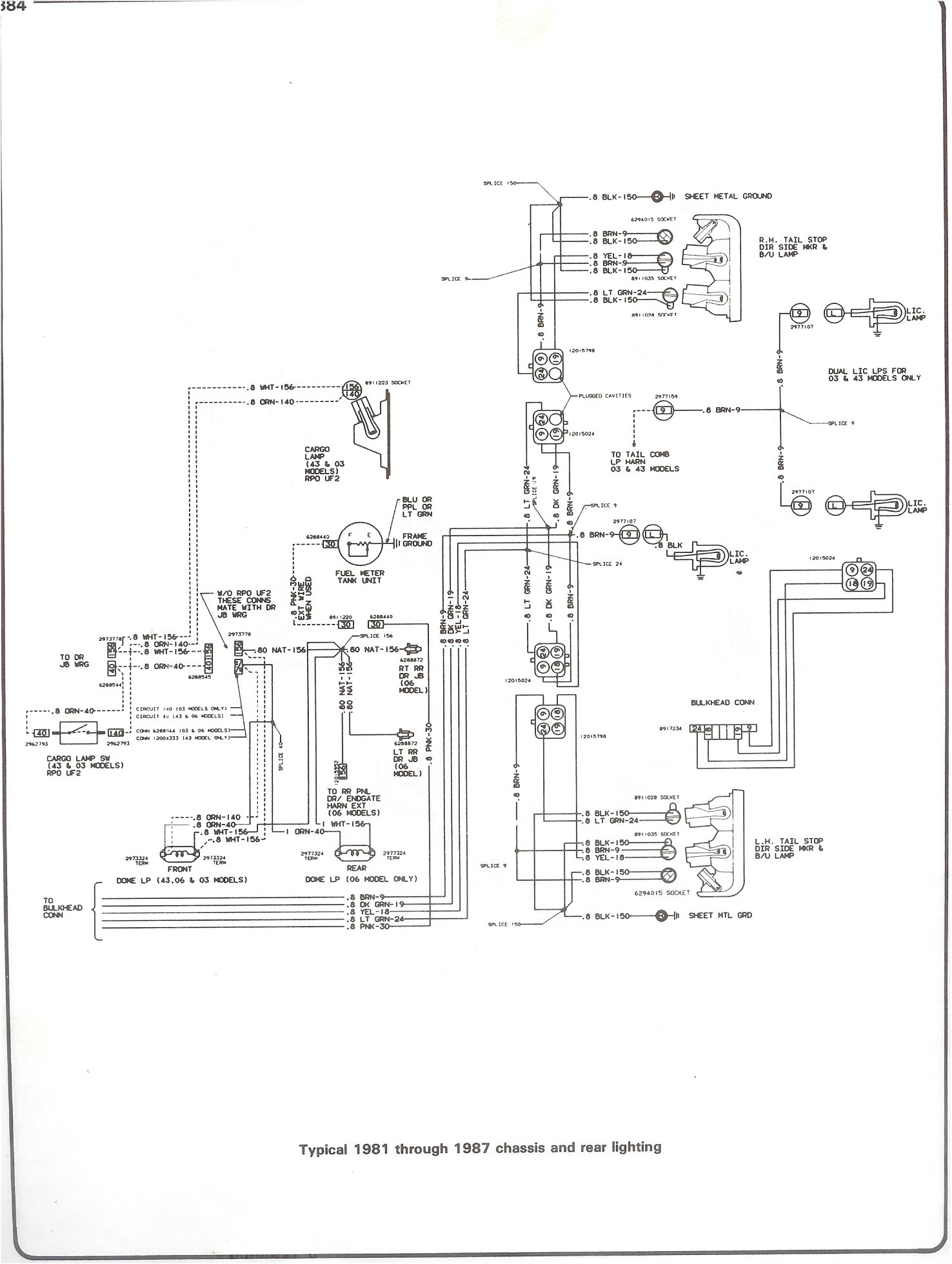
Limitorque l120 wiring diagram. Then enter drawing number or select options. Flowserve limitorque l series multi turn electric actuators have a solid. When combined with a limitorque wg or hbc series quarter turn gear. Flowserve limitorque l120 10 user instructions 36 pages actuation systems. Limitorque l120 wiring diagram sample architectural wiring representations show the approximate areas and affiliations of receptacles illumination as well as long term electric solutions in a structure. Acrodynes limitorque l120 40 decant on test.
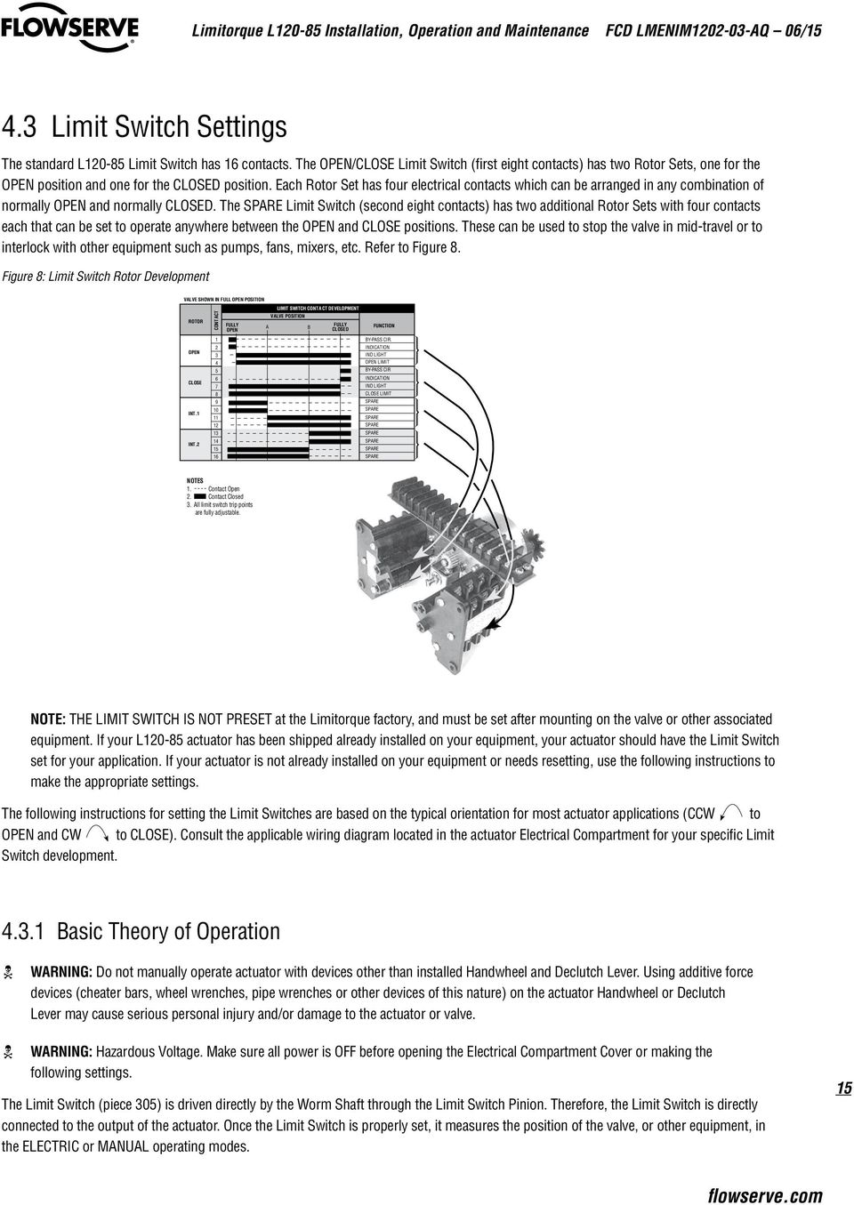
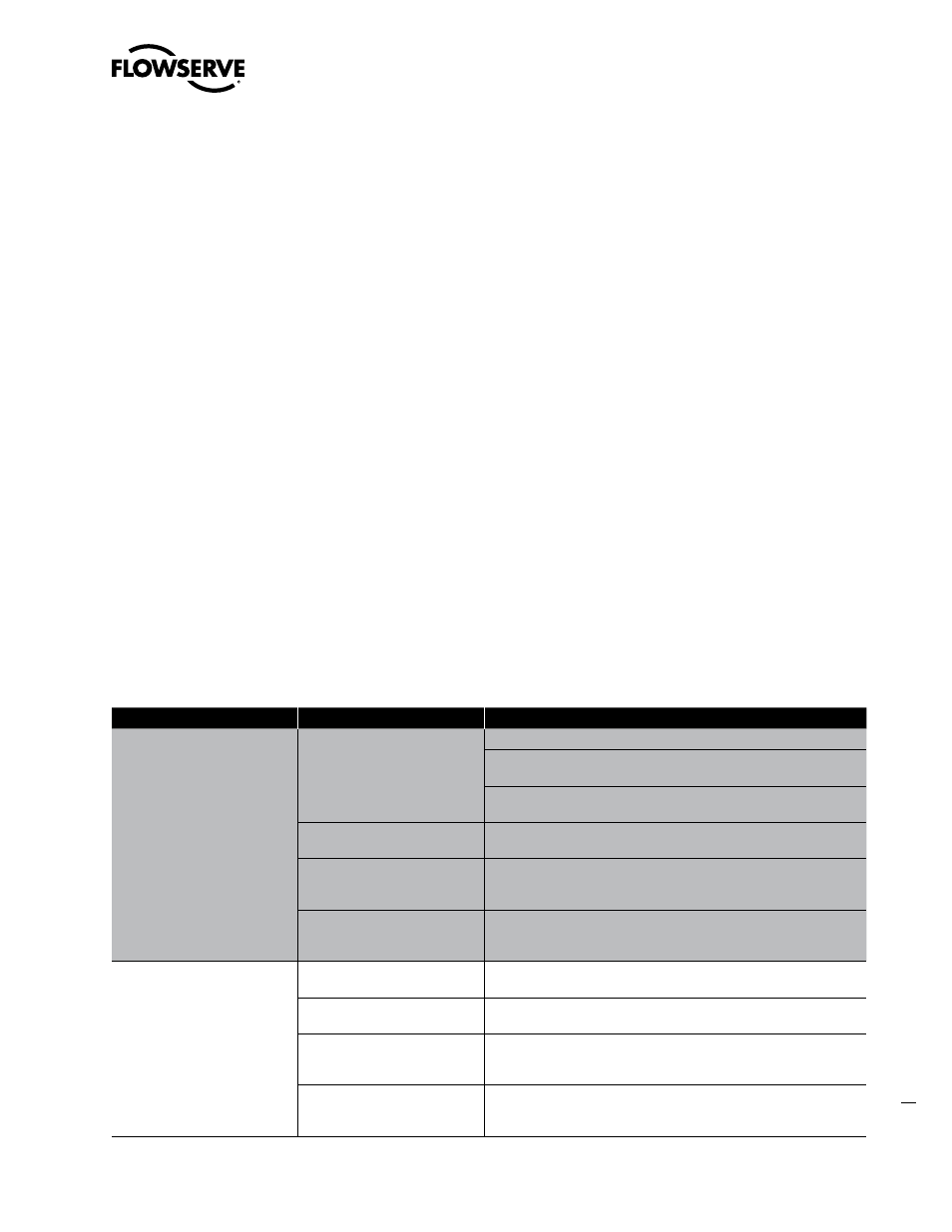
It shows how a electrical wires are interconnected and will also show where fixtures and components may be attached to the system. Limitorque actuation systems l120 series fcd lmenim1201 05 a4 0318 figure 43 setting the open and closed contacts closed open position position 453 combination of contacts refer to figure 42 the rotor segments can be separated and rotated through 90 degrees to give various combinations of normally open or normally closed contacts to each rotor. Flowserve limitorque actuators are available with a wide range of standard and optional features. Whether used with gate valves globe valves penstocks or sluice gates versatile l120 series actuators operate without modification in any rising or non rising stem application for linear action valves. Mxa wiring diagram qx wiring diagram. L120 bic wiring diagram share.
L120 bic wiring diagram title of each drawing downloads the file. Acrodyne technical support limitorque wiring diagrams. All l120 units are supplied with 8 contact limit controller is supplied switches 4 switches on each of 2 rotors. Refer to the wiring diagram on page 52 for reference and consult the applicable. Interconnecting wire routes might be revealed around where particular receptacles or fixtures should be on a typical circuit. Drawing number description unit size.
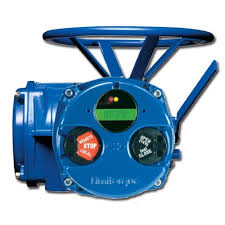
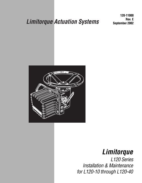
A wiring diagram is a simple visual representation of the physical connections and physical layout of your electrical system or circuit. Figure 1 limitorque l actuator. Consult the relevant wiring diagram for limit switch contact closed generally required if uec 3 family fig 2 development. Two rotors are used a if contact is normally open no for end of travel indication. 11 purpose this installation and maintenance manual explains how to install and maintain the l120 10 l120 20 and l120 40 actuators. Limitorque l120 wiring diagram what is a wiring diagram.
Be aware of these features and their role in the setup and operation of the actuator.
Gallery of Limitorque L120 Wiring Diagram