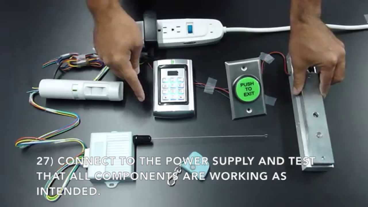
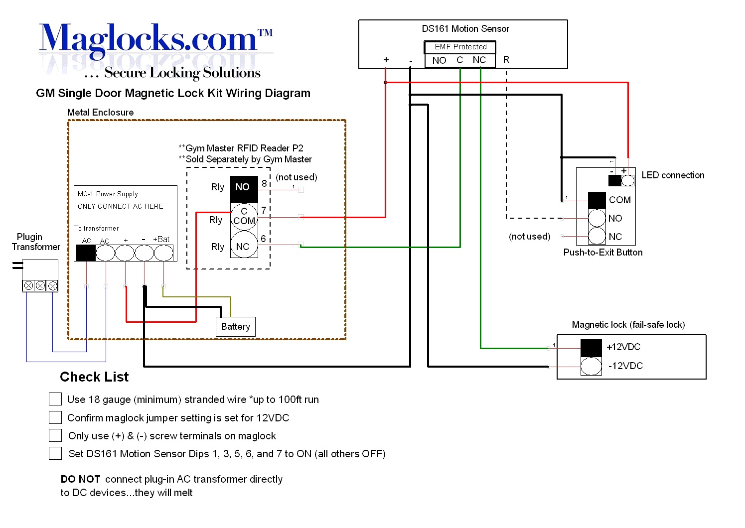
Lock n a box kits. Complete single door laundromat magnetic lock kit without or with key switch access systems.
Door Entry Wiring Diagram 2 Fail Safe High Power Magnetic
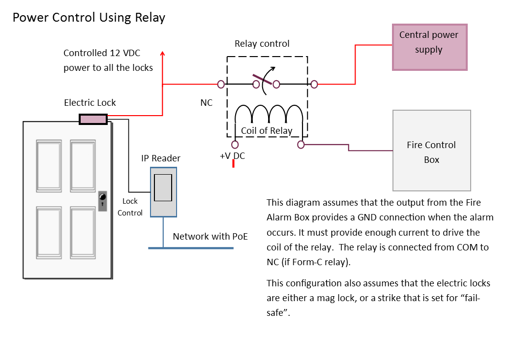
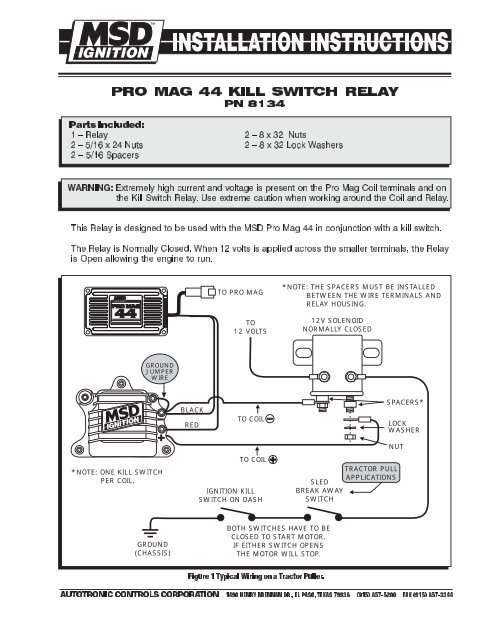
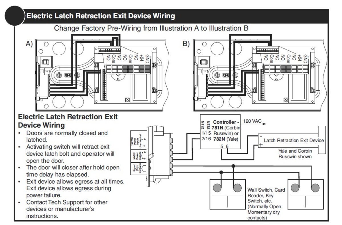
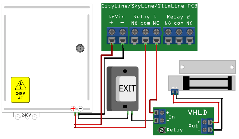
Mag lock wiring diagram. Wiring instructions magnetic lock or fail safe strike with button keypad maintained button and remote receiver. This will conver t the ac to dc. A wiring diagram is a streamlined conventional pictorial depiction of an electrical circuit. Magnetic lock wiring instructions models 600s 600l 600d 1200s 1200l to remove the header plate it may be necessary to remove the wiring compartment screw. Push button release electric strike. Refer to the interconnector manual usually same manual as access control panel since they are often packaged together and note which wires should be connected to.
If this is not available you may use an ac power source and wire inline a full dc output or you can damage the magnetic lock or fail safe strike. Complete single door laundromat magnetic lock kit kp 200 digital keypad wiring diagram. Chexit wiring diagram. It is essential that the surfaces of the armature and the magnetic lock seat. Wired in series power supply for fail safe strikes and magnetic locks should be dc. Hot electric trim.
Insert interconnector wires into magnetic lock. Alarm controls lock n a box kit lnb 6 with kp 100 keypad. Collection of magnetic door lock wiring diagram. Lever locks for fire doors. Two single doors with panic bars. Unscrew the access panel on the magnetic lock using the phillips head screwdriver.
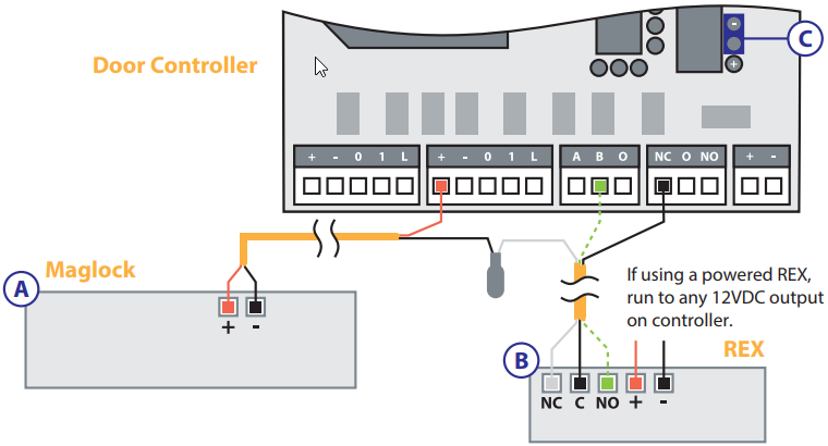
Is there an rga form. It shows the components of the circuit as simplified shapes and also the power as well as signal connections in between the gadgets. Two single doors with panic bars. A long wiring compartment screw can be used to increase security by limiting access to the header plate mounting. Mag lock wiring diagrams. Mag lock w push buttons.
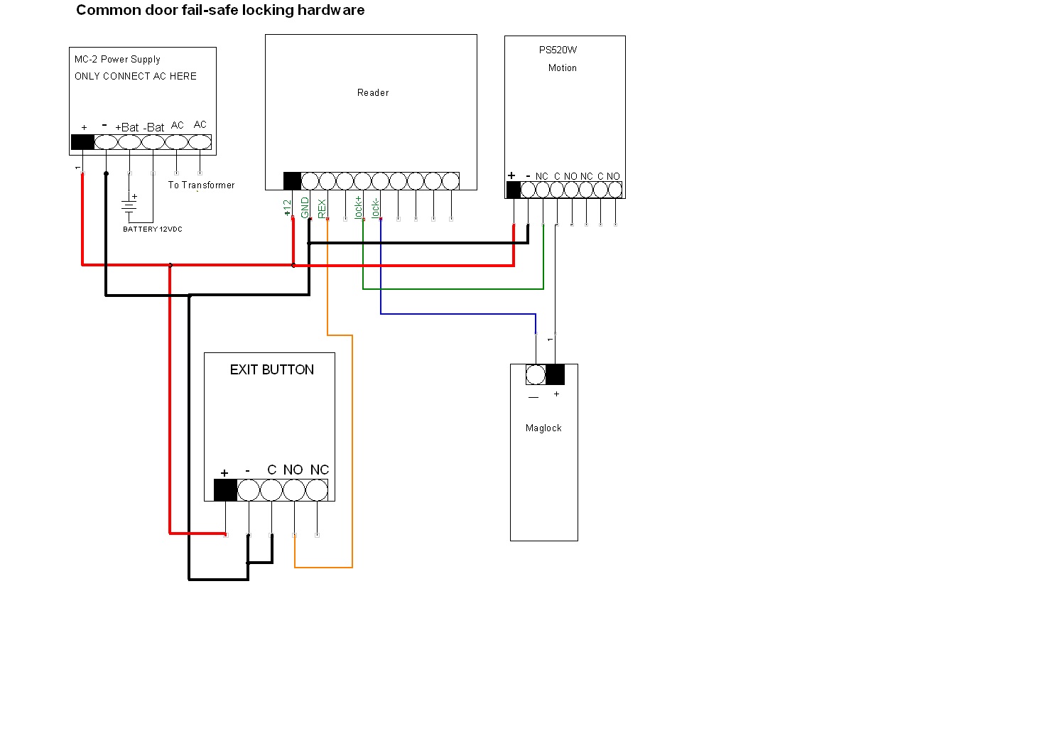
In the simple diagram above you can see that the electricity travels in an unbroken loop. Wiring diagram for mag lock w push buttons wiring diagram biometric push button. The inside of the access panel includes a diagram with labels. If this is not available you may use an ac power source and wire inline a full wave bridge rectifier. Emergency release tool. It starts at the positive terminal of the power supply travels through the exit and entry switches into the positive terminal of the magnetic lock and out through the negative terminal of the mag back in through the negative terminal of the power supply.
Gallery of Mag Lock Wiring Diagram