Whether you have the mallory unalite or dual point with or without our power amplifier you will find below a wiring diagram to suit and also the original instructions that come with the mallory distributors. 10 start the three wires of the mallory unilite module through the hole in the nose 14 route the wires from the unilite module to the ignition coil carefully 16 follow a factory shop manual to set the timing for your particular enginewiring diagram for mallory distributer dont worry if your coil doesnt look like this american one or.
Australian Rr Forums Installing A Replacement Distributor
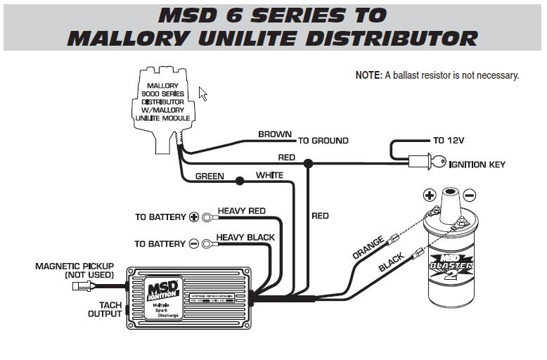
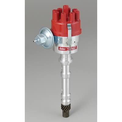
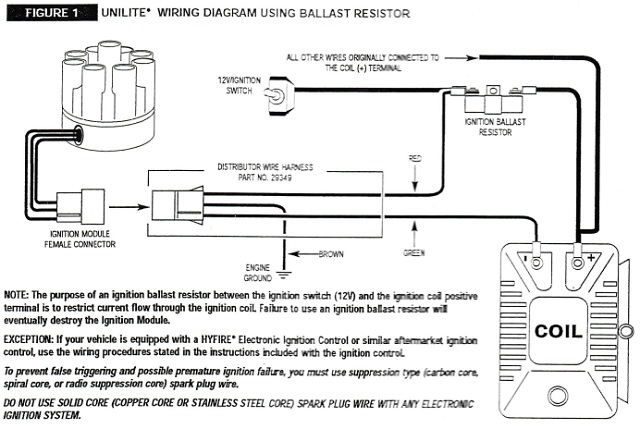
Mallory unilite distributor wiring diagram. Before installing the. Figure 1 unilite wiring diagram using ballast resistor coil ignition module female connector engine ground all other wires originally connected to the coil terminal distributor wire harness part no. A staple back in the 70s the tried and true mallory unilite was the original performance distributor. As a matter of fact a bad diode trio in a conventional alternator can do the same damage. Supplied with a quality cap and rotor the mallory unilite also provides a fully adjustable mechanical advance to dial in the perfect timing curve for a multitude of engine. 1 distributor wire harness.
Just simply click an image below for the correct instructions pack that would be supplied with your mallory distributor or for just a. Collection of mallory ignition wiring diagram. 29349 loom resistance wire brown green red. 29349 ignition ballast resistor brown green red. Parts included in this kit. The easy three wire hookup of the unilite makes running a stock coil a mallory performance coil and even a mallory hyfire cd ignition a snap.
Install the remaining spark plug wires from the original distributor cap to the unilite distributor cap in the same sequence. This can send a 30 or higher volt spike through the system. The mallory unilite distributor is back. 1 unilite distributor. It shows the components of the circuit as streamlined forms as well as the power and also signal links between the tools. Unilite distributor vacuum chamber and the carburetor.
Distributor cap post above the mark on the unilite distributor housing where the rotor had pointed. A wiring diagram is a simplified standard pictorial depiction of an electrical circuit. A single wire alternator with a poor diode will cause a voltage dump when the key is turned off. Unilite distributor vacuum chamber and the carburetor. A legend returns the tried and true mallory unilite distributor line is back. The mallory unilite is sensitive to voltage spikes.
A legend has returned. The purpose of an ignition ballast resistor between the ignition switch 12v and the ignition coil positive terminal is to restrict current flow through the ignition coil. Its small compact housing along with the elimination of old fashioned points made it popular among performance enthusiasts when it came to engine performance.
Gallery of Mallory Unilite Distributor Wiring Diagram