The fan im connecting is manrose gold with over run timer. Bathroom fan with timer wiring diagram collections of bathroom fan with timer wiring diagram collection.

Ym 5934 Wiring A Bathroom Fan Wiring Diagram
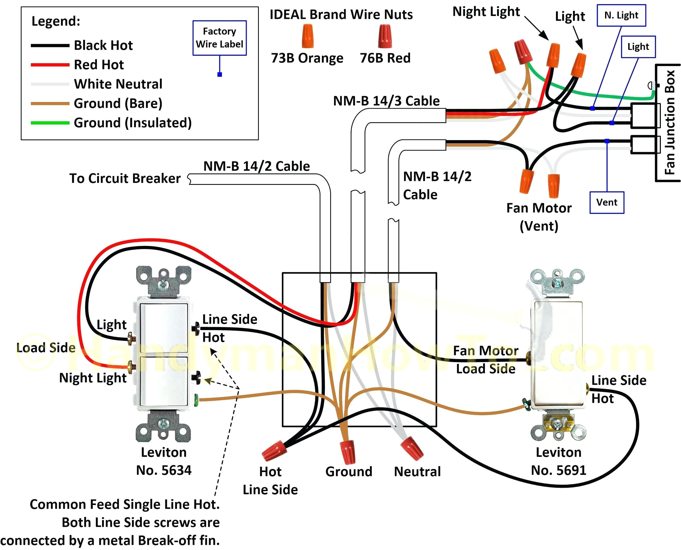
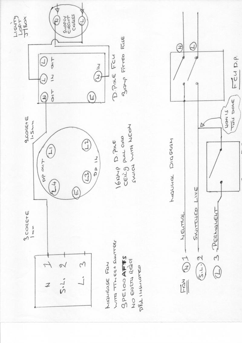
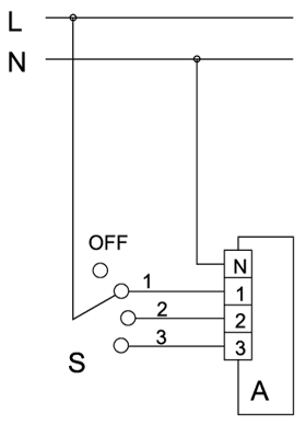
Manrose fan timer wiring diagram. 11 timer fan wiring diagram t n l timer switch neutral live fig 12. It shows the components of the circuit as simplified shapes and the gift and signal links between the devices. Wiring diagram for bathroom fan 2019 heller exhaust fan wiring. Installing the switched fan. Low speed wiring timer adjustment knob. Wiring of timer model.
Wiring diagram for bathroom fan simple wiring bathroom fan light. Fits new or existing fans small enough to fit most common flush boxes. Switches fans from 200w down to 20w adjustable run on time start delay. Refer to internal wiring label and diagram 2 of this instruction for correct connection. This fan requires a neutral switch live and permanent live supply. Manrose fan wiring diagram wiring diagram is a simplified adequate pictorial representation of an electrical circuit.
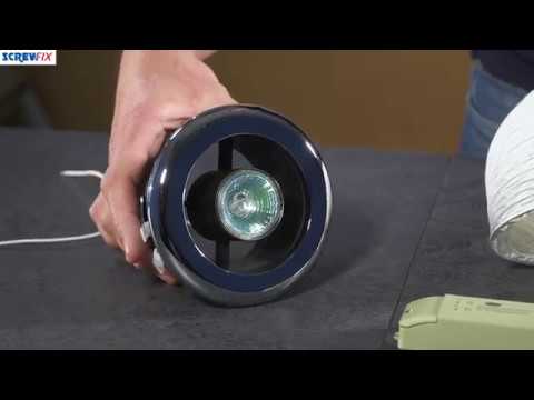
Hi this video is about wiring a bathroom extractor fan wiring fan to the three pole fan switch isolator and pull cord switch. Range is the id150 tube fan with a top performance of 230m3hr 64 litres per second. Available with or without a timer the sf100120150 fan kits are supplied complete with a fan unit one length of pvc flexible ducting one internal white and one external wall grille fixing screws plugs and straps to secure the duct to the grilles. Fully adjustable run on timer. Simple wiring diagram for bathroom fan with timer. Cord is damaged it must be replaced by the.
High speed wiring figure 13. Technical support 09 259 1662. Manrose is proudly distributed by simx limited po box 14 347 panmure auckland nz. Timing adjustable from 1 sec to 90 mins. The run on time is dependant on how long the fanlight has been running. The fan can either be operated from a separate pullcord switch fitted to the ceiling of.
And neutral supply refer to internal wiring label for correct connection. The supply for this can be taken from most existing circuits providing the switched fused unit sfu is present at the start of the installation and appropriately fused to protect the sub circuit cabling and accessories. Diagram showing wiring method for an independently switched extractor fan. Includes resitor for use with lower wattage fans 50w 20w.
Gallery of Manrose Fan Timer Wiring Diagram