Trane ycd wiring diagram. I have the wiring diagram for the intelliweld.

Welding Remote Custom Made Includes Miller 14 Pin And Lincoln 6 Pin Adapters Ebay
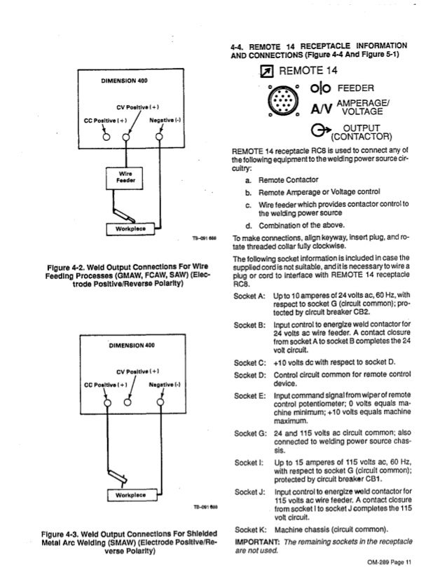
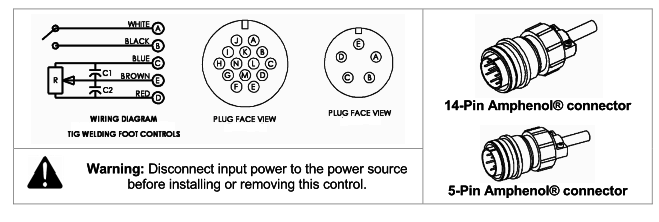
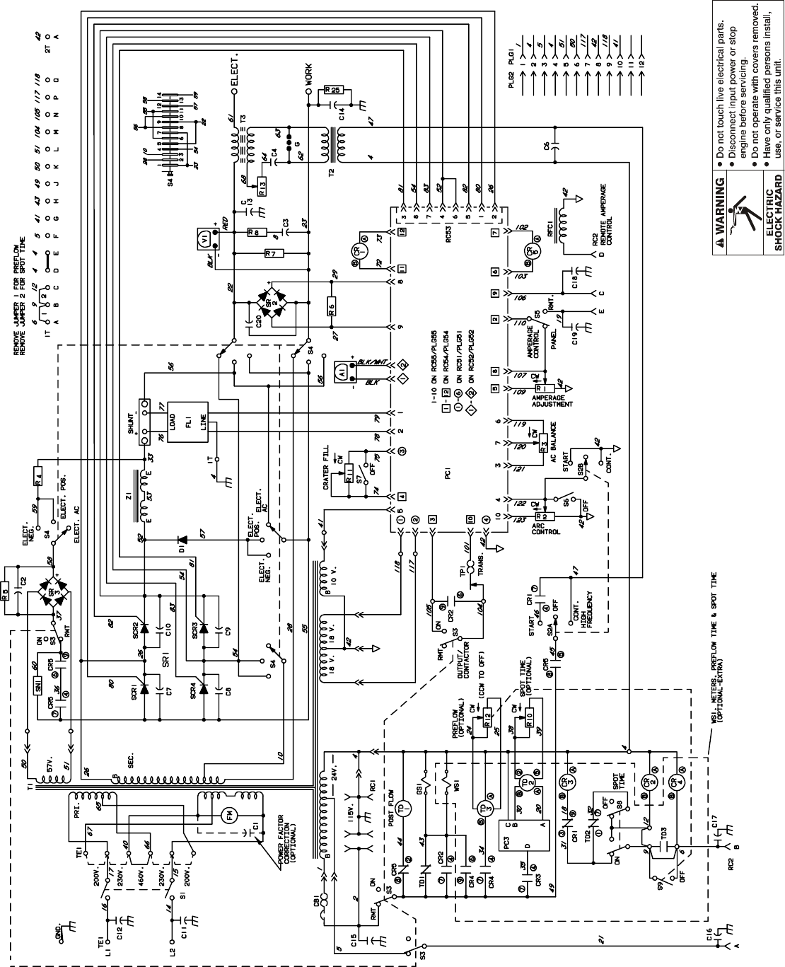
Miller 14 pin connector wiring diagram. With the machine turned on the cooling fan may or may not run with the machine on. Singer foot pedal wiring diagram. Circuit diagram for rhc 3 gd25b circuit diagram no. Miller style 14 pin receptacle diagram. Suitcase extreme 12rc 14 pin breakout the user manual for the hf 251d 1 provides a bit more detail regarding the pins you asked about abcd e however the. I was going to try to hook a 14 pin up to it as well.
I could just wire the 10 pin to the sm 1 without too much trouble. Sa 150 671 diagram 5 2. Incorrectly installed or improperly grounded equipment is a hazard. Sub and amp wiring diagram. 36 volt trolling motor wiring diagram. Circuit diagram for remote hand control used with transformer arc welding power source circuit diagram no.
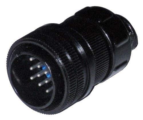
You can buy the cable to adapt the sm 1 to a 10 pin connector from miller4less but i figure why pay 60 if i have the 10 pin connectors. Miller 14 pin connector wiring diagram. Sa 094 232 a diagram 5 4. Normally of the machine has a pilot light that lights when the machine is on. How to identify the 14 pin connector on your machine. To determine which control will work with your welder check the number of pins on your welders remote receptacle and the shape of the connector to make sure.
For miller welding machines that usa a 14 pin plug. Circuit diagram for rhcs 3 circuit diagram no. Electric shock can kill. 7 pin trailer wiring harness diagram. Sa 094 231 a diagram 5 3. C810 1425 tig foot pedal for miller rfcs 14 043554 with 14 pin plug this tig foot control cross reference guide will help you determine which foot pedal can be used with your welder.
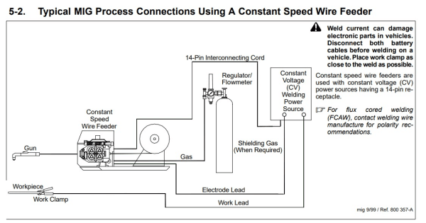
Cpcc 1500 deltaweld 300 302 402 451 452 602 651 652 852 dimension 302 372 400 452 562 650 652 812 dynasty 300 sd dx lx. Wire welding the wire wire reel drive roll housing and all metal parts touching the welding wire are electrically live. Case 444 garden tractor wiring diagram. Wear a safety harness if working above floor leveldo not touch live electrical parts. With a meter on ac voltage check between pins a b.
Gallery of Miller 14 Pin Connector Wiring Diagram