In the sample box diagram a complete nmea 2000 network is shown and the parts included with the sensor are shaded. Assortment of nmea wiring diagram.

How Do I Connect A Maretron Field Makable Connector Or Field
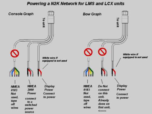
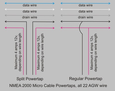
Nmea 2000 power cable wiring diagram. A wiring diagram is a simplified conventional photographic depiction of an electric circuit. Have everything wired and am having issues. The nmea 2000cable system includes five wires within a single waterproof cable. In this case you would power your nmea network by connecting one of your lms or lcx unit power cables marked nmea power to a switched power source. The a2k mpt 1 is a simple safe and efficient method of powering an nmea 2000 network. Wellborn collection of nmea 2000 wiring diagram.
In this example a t connector is included with a garmin gfs 10 fuel sensor. Nmea 2000 signals can be hampered by resistance which causes a reduction in voltage. 2020 fountain 34 te. Ethanol gasoline purchasing caution for boaters. So have spent the weekend so far hooking radar up. A wiring diagram is a simplified conventional pictorial depiction of an electrical circuit.
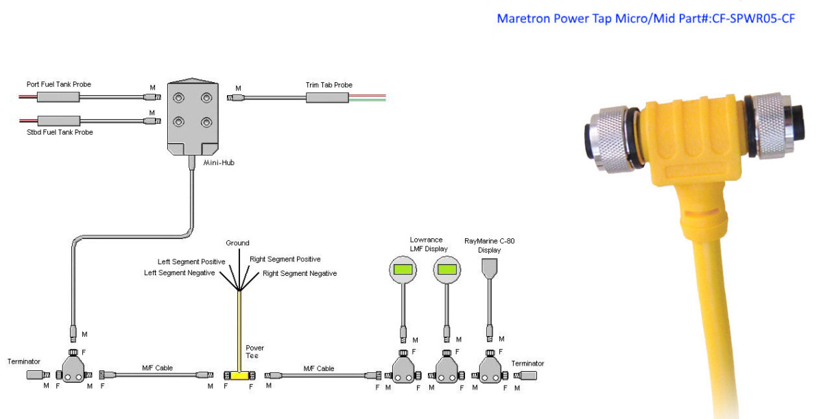
Two signal wires power and ground wires and a drain wire. November 22 2018 by larry a. The nmea 2000cable system uses a trunk sometimes referred to as the backbone and drop line topology as shown in figure 1. If you require a longer cable run to connect an item such as a transducer or sea surface temperature sensor use a t junction to either at the end or the middle of the run to tie in 12 volt power. In the sample box diagram a complete nmea 2000 network is shown and the parts included with the sensor are shaded. A nmea 2000 power cable an additional dropbackbone cable and additional t connectors are not included with a gfs 10 fuel sensor.
Proper connections ensure that nmea 2000 communications function as intended. The maximum length for a single drop cable is 20 feet. Next was the ais and nmea 2000. When connecting nmea 0183 devices with two transmitting and two receiving lines it is not necessary for the nmea 2000 bus and the nmea 0183 device to connect to a common ground. Six tips for ensuring proper nmea 2000 connections. In this example a t connector and two terminators are included with a garmin gfs 10 fuel sensor.
It reveals the parts of the circuit as streamlined forms and also the power and signal links between the gadgets. The micro power t can easily provide power to the nmea 2000 bus with micro fit connectors to enable plug and play connectivity. Gpsmap 4000500060007000 wiring diagram gpsmap 40005000 or gpsmap 60007000 power cable 12 vdc power source mercury zeus and axius system. A nmea 2000 power cable terminators an additional dropbackbone cable and additional t connectors are not included with a gfs 10 fuel sensor. What to look for in a jet powered boat.
Gallery of Nmea 2000 Power Cable Wiring Diagram