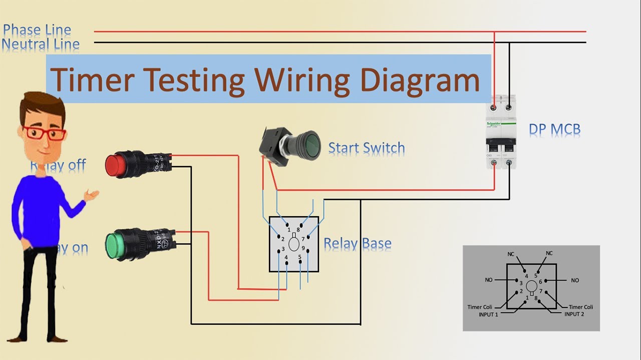
A wiring diagram is a streamlined conventional photographic depiction of an electric circuit. The activation of loads parallel to the start input is not permissible when using ac control voltage see diagram below.
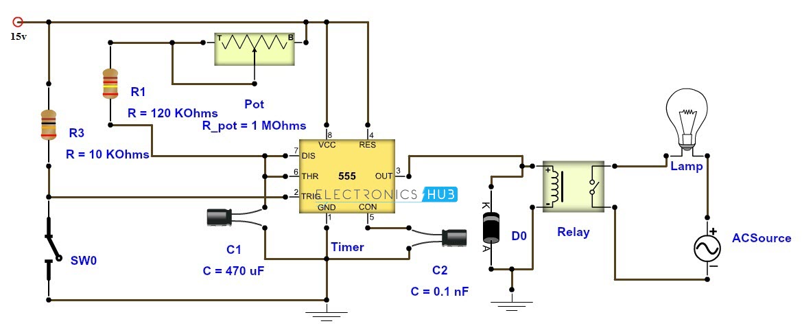
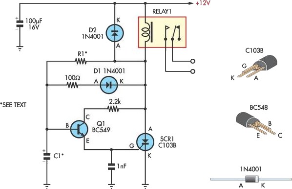
Adjustable Timer Circuit Diagram With Relay Output
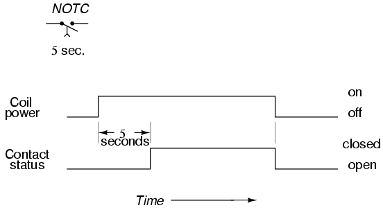
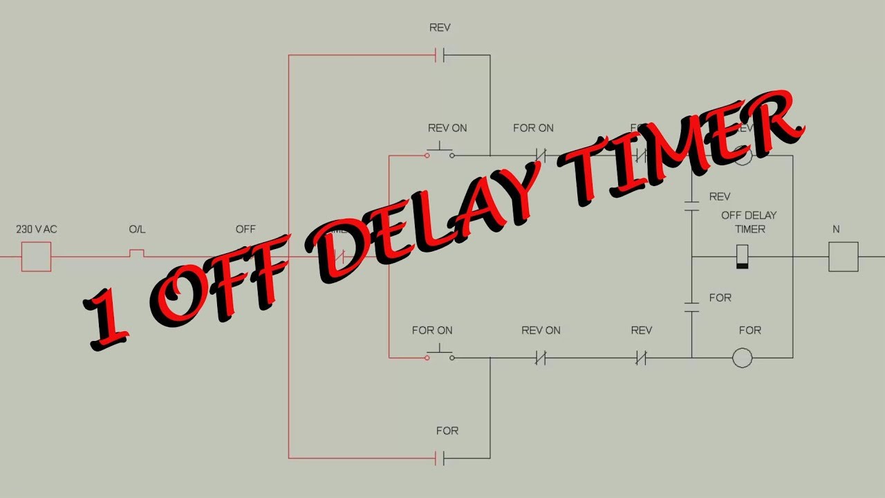
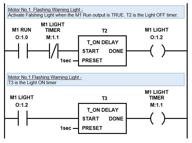
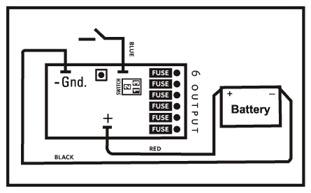
Off delay timer wiring diagram. If voltage is removed before time out the time delay resets click here to see fig. Such off delay timers are used in the motor cooling system cooling systems are generally designed with the cooling motors and they run with the main motor to cool the motor after the main motor is stopped the cooling motor will be made to run for some time with the help these off delay timers. When the time has expired the contacts close and remain closed until voltage is removed from the coil. Collection of dayton off delay timer wiring diagram. The normally open off delay contact is called normally open time open and the normally closed is called normally closed time close contacts. It shows the components of the circuit as streamlined shapes and also the power and signal connections in between the tools.
Such timers are called off delay timer. Assortment of time delay relay wiring diagram. With the two voltage version only one voltage range must be connected. Connect the circuit as shown in the diagram and check itcheck for on time and off time using ton 0693r1r2c1toff 0693r1c1 formulaemake sure that off time is not too low. Same potential must be applied to a1 and b1 or a3 and b3. Wiring of off delay timer i have purchased an off delay timer to basically run a boiler pump 120v for a minute after boiler shuts off.
Off delay timers are with aux. A wiring diagram is a simplified standard pictorial depiction of an electric circuit. The contacts of the off delay look like a single pole switch with an arrow pointing down from the switch. When using an off delay timer nothing happens when. Voltage refer wiring diagram fig1. The wiring diagram is below.
It reveals the elements of the circuit as simplified shapes as well as the power and also signal links between the gadgets. The first circuit diagram shows how a transistors and a few other passive components may be connected for acquiring the intended delay timing outputs. With an on delay timer timing begins when voltage is applied. Like on delay timers off delay timers can be easily identified. The off delay timer coil is labeled the same way as other loads are identified in ladder diagrams with the exception of the abbreviation of td to indicate time delay. So far we have learned how to make simple delay off timers now let us see how we can build a simple delay on timer circuit which allows the connected load at the output to be switched on with.
Gallery of Off Delay Timer Wiring Diagram