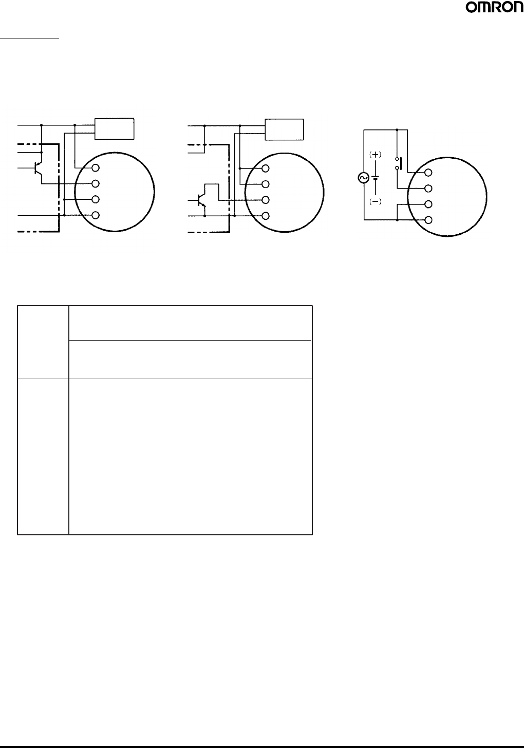
48 to 125 vdc h3cr f 48 125dc h3cr f8 48 125dc h3cr f 300 48 125dc h3cr f8 300 48 125dc flicker on start 100 to 240 vac h3cr fn 100 240ac h3cr f8n 100 240ac h3cr fn 300 100 240ac h3cr f8n 300 100 240ac. Shaded areas show internal connections.

Omron H3bh 8 Timer Ebay
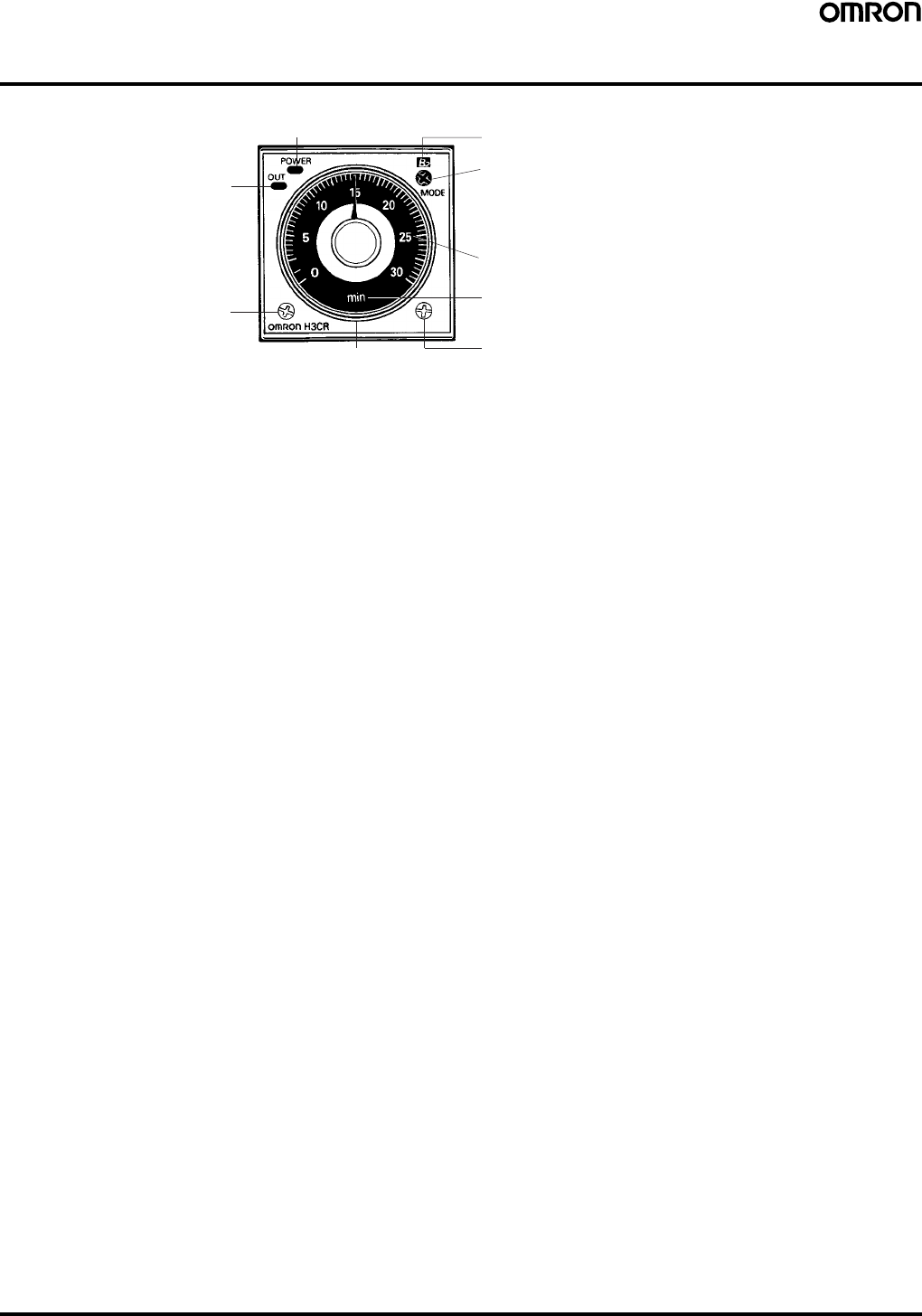
Omron h3cr f8 wiring diagram. Omron h3cr a8 wiring diagram gallery contemporary omron relay wiring diagram model electrical circuit. H3cr timer pdf manual download. A wiring diagram is a simplified conventional photographic representation of an electric circuit. Timing starts at the leading edge of the start input. The values are for when the terminals 2 and 7 and terminals 10 and 6 are short circuited and include the consumption current of the input circuit. It reveals the parts of the circuit as simplified forms as well as the power as well as signal links in between the tools.
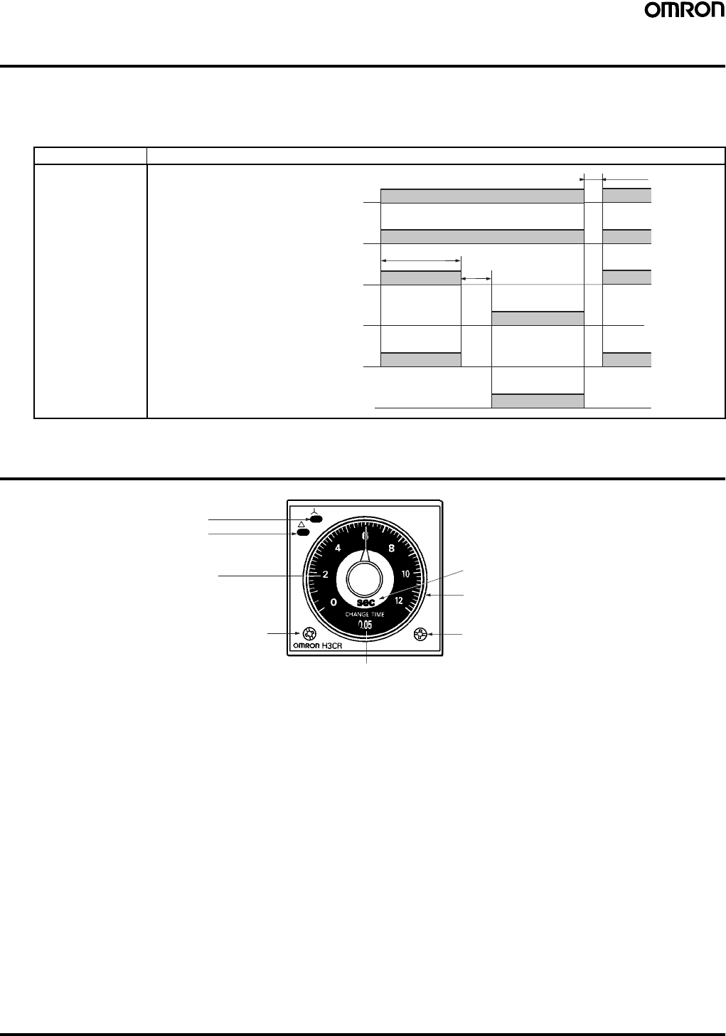
Omron h3ca a wiring diagram beautiful help me wire up an omron h3y 2. H3cr a h3cr as six function timers mode a on delay signal startsignal reset power is applied continuously. H3cr a h3cr as h3cr ap h3cr a8 h3cr a8s h3cr a8e h3cr f h3cr fn h3cr f 300 h3cr fn 300 h3cr f8 h3cr f8n h3cr f8 300 h3cr f8n 300 h3cr g8l h3cr g8el. The output relay is energized when the. H3cr h3cr 3 timing charts in the schematic diagrams each thick line indicates the external wiring. Solid state timer h3cr series.
Vdc power supply are available the h3cr a 302 and h3cr a8 302 for details consult your omron sales representative. Omron relay my4n wiring diagram. View and download omron h3cr manual online. Variety of omron h3cr a8 wiring diagram. Contemporary omron relay wiring diagram model electrical circuit.
Gallery of Omron H3cr F8 Wiring Diagram