Now connect the wire coming in from the engine bay to the connection on your switch and connect the wire with the resistor on it to the and load connections on the switch. Go back under the hood and reconnect the red 12v cable to the battery.
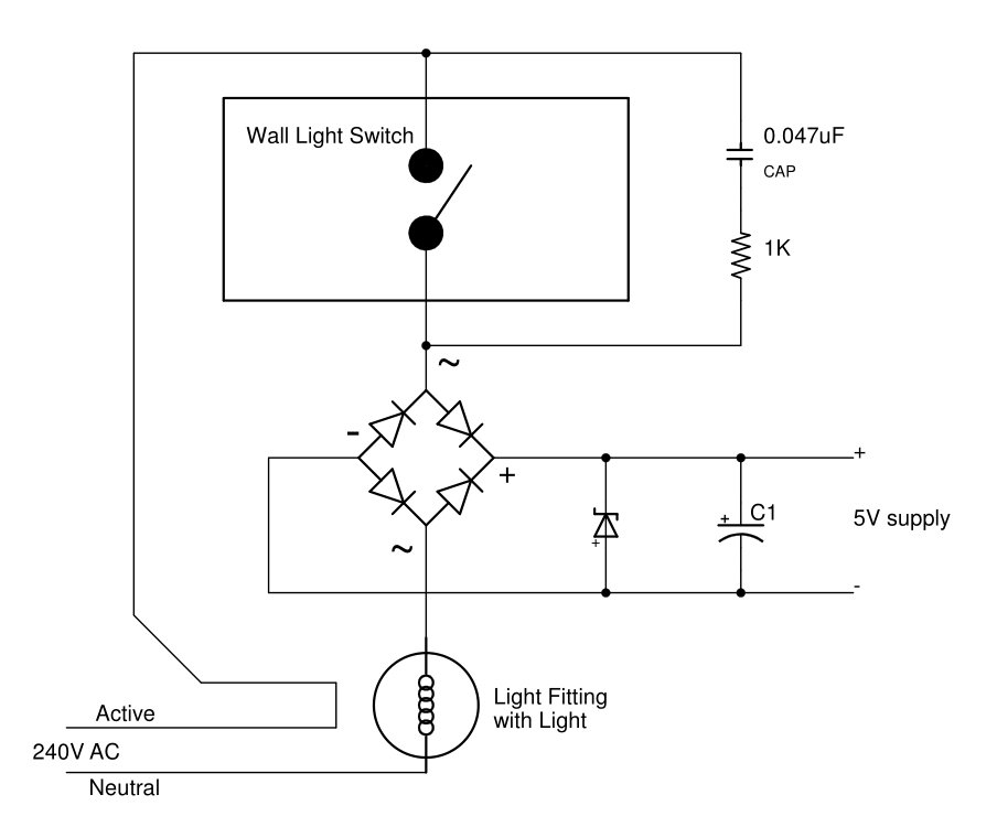
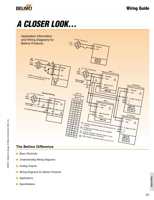
Remote Controlled Light Switch Retrofit With Manual
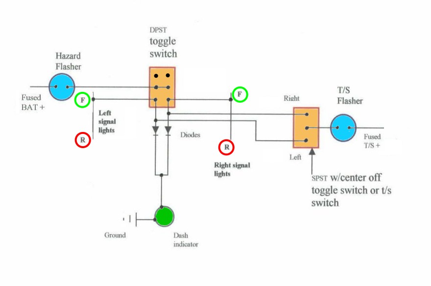
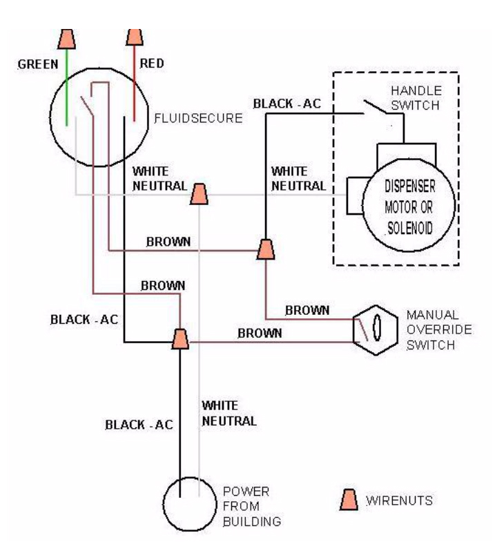
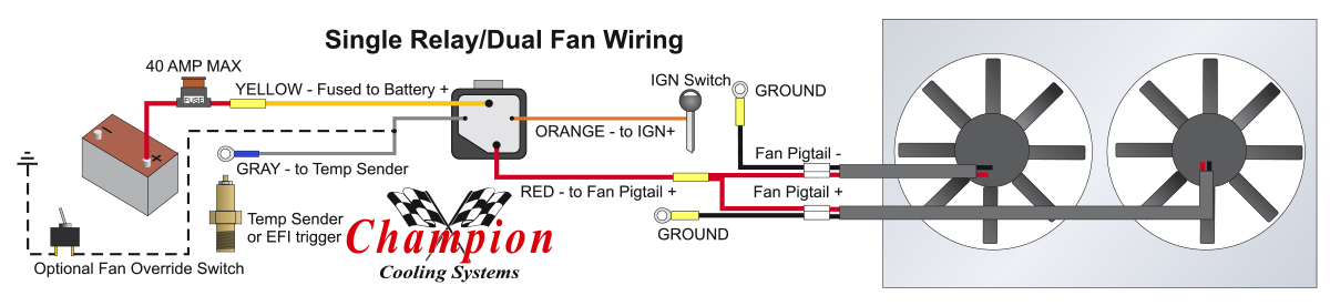
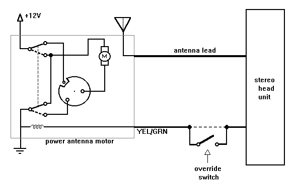
Override switch wiring diagram. Proper way is to use a relay to switch the fan then either the rad switch or your override switch can switch the relay. Fan override switch in stock part number. 3pdt switch positive ground circuits. Im assuming that i should be using a diode on the output signal wire from the ecu to the signal input terminal on the relay. Wiring manual override switches. The basic information about this can be found in power switching article.
3 backlit bilge rocker switch wiring diagram. The diagrams above are for a plastic switch. Sealed 3m wiring loom and connection diagram. If two or more sensors are required to operate all of the lights additional sensors can be connected by extending the nlsle wiring to additional sensors. There are three big terminals on it with the fan they are 12v supply to the switch and then slow and fast to the fan you want to use the first two to control the rad fan. True bypassled indicator dc jack for a pnp positive ground circuit with a negative tip power supply.
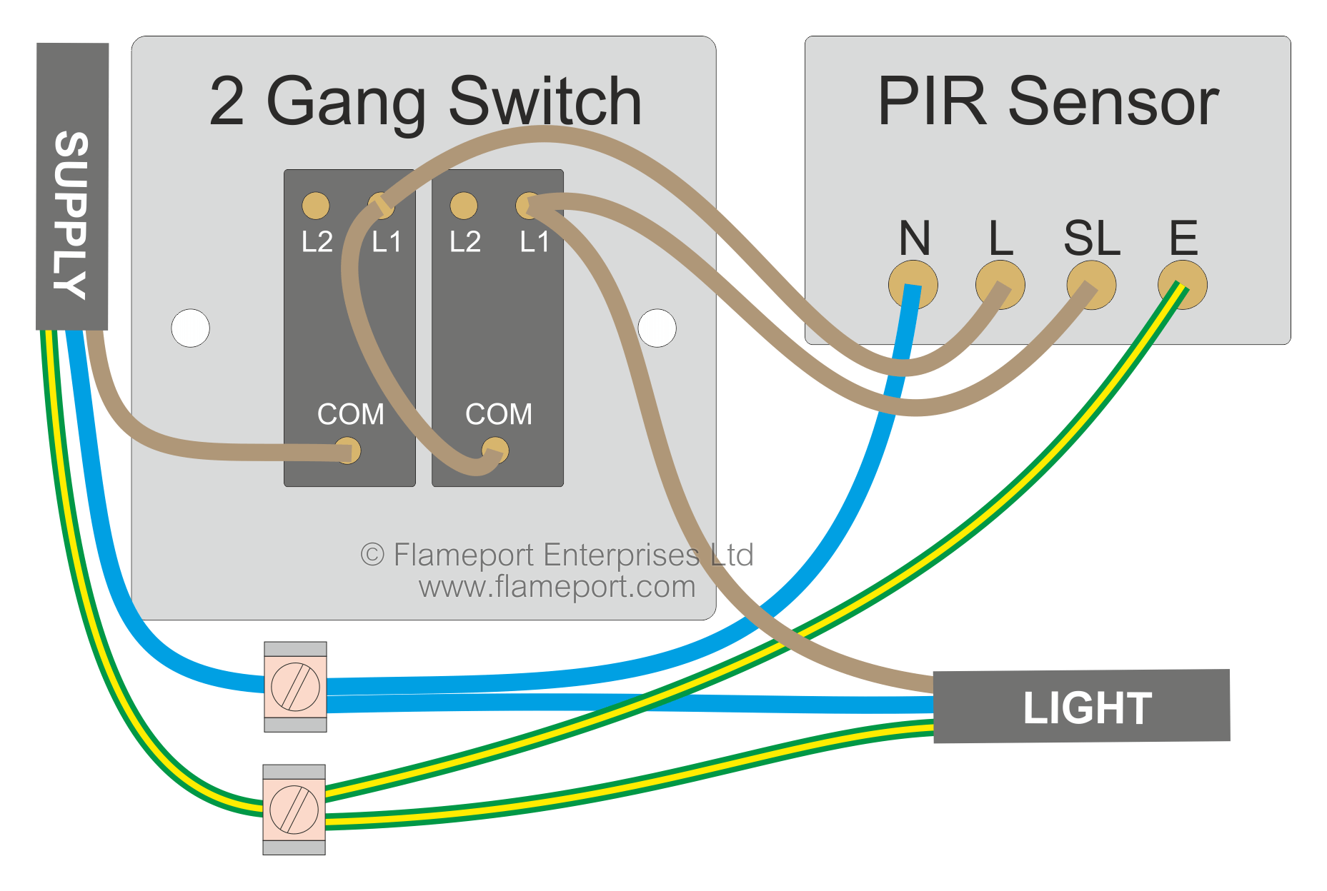
This is a simple how to video on creating a fan override switch for your motorcycle as clear and simple as humanly possible with a diagram at the endwill not work for a motorcycle with ecu. Pir override switch wiring diagram with manual pir with manual override wiring diagram passive infrared pir and ultrasonic technologies into one unit users can override this function by the relays are programmed independently for either auto on or manual on pir override switch wiring diagram community screwfix electricians talkfeb 14 2008 pir. True bypassled indicator dc jack input grounded for a pnp positive ground circuit this is the. Here are some variations of wiring pnp positive ground circuits with a 3pdt switch. Learn more about how our awesome backlit switches work here even that one is still pretty straight forward though here are some diagrams that show the single jumper required on the back of the switch. For both diagrams above one or more lights can be connected to the pir sensor nsl and e terminals.
Of the three bilge pump switches the only one thats not extremely simple is the backlit automanual bilge pump switch. Perfect for 4x4 applications such as wading. Attach that wire to the grounding point you found in step 27. Sw blk 3 way rotary switch for use with a revotec fan controller enabling the fan to be manually controlled either on off or automatic. I have a question about wiring in a manual override switch for things such as a cooling fan or secondary fuel pump. Metal switch or box.
Black anodised mounting bracket kit.
Gallery of Override Switch Wiring Diagram