The paragon series auto voltage defrost timer is designed competitive voltage specific mechanical defrost timers eliminating wiring diagrams. Here is a picture gallery about 20 wiring diagram complete with the description of the image please find the image you need.

120v Defrost Timer
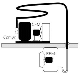
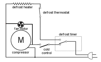
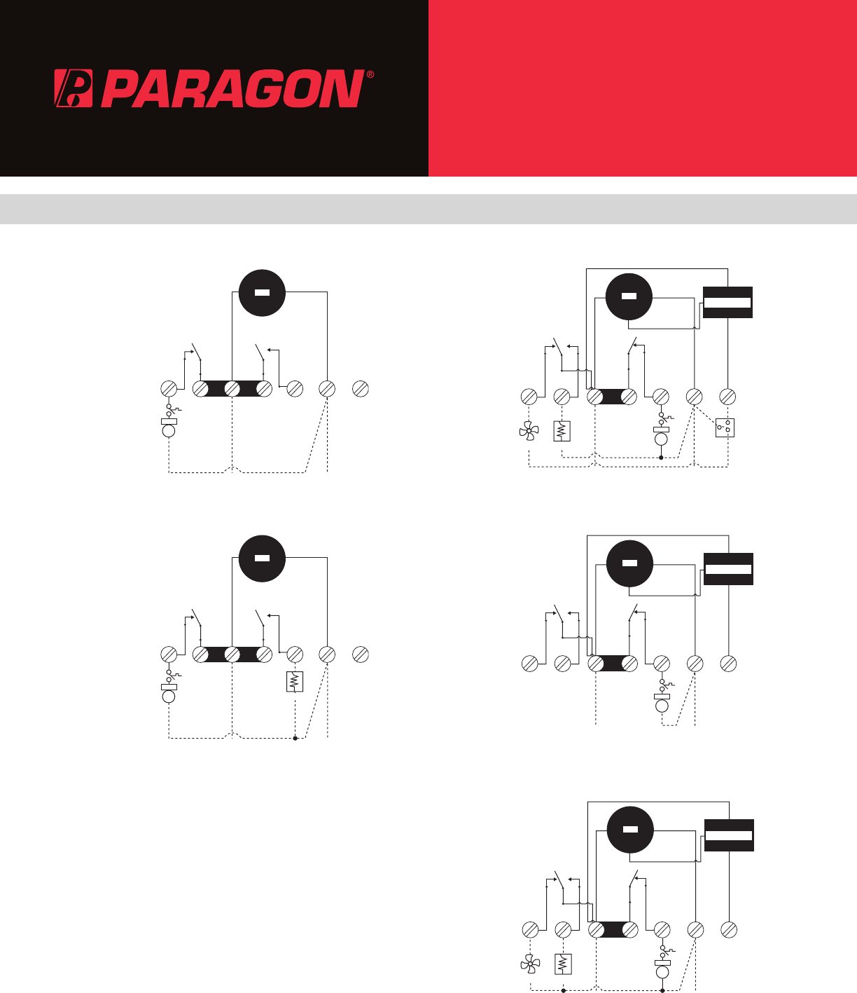
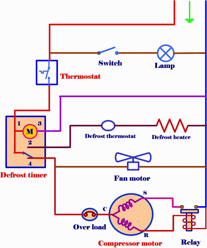
Paragon defrost timer wiring diagram. Paragon defrost timer wiring diagram paragon defrost timer wiring regarding 20 wiring diagram image size x px and to view image details please click the image. Paragon 8141 00 wiring diagram refrigerator defrost timer wiring diagram collection cold zone walk in freezer schematic diagram collection of download wiring diagram. Hot gas valve turns on for defrosting. The cycle works like this. It reveals the elements of the circuit as streamlined shapes and also the power as well as signal links in between the tools. Paragon defrost timer wont turn.
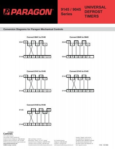
Convert to convert to convert to n 1 4 32 x. Paragon defrost timer 8145 20 wiring diagram gallery. Timer switches on and activates defrost cycle. Fixyai need a wiring diagram for a paragon 00m fixya. Cycle limit switch is temperature or pressure sensitivesolved. The latest paragon defrost timer universal defrost timers udt universal defrost timer wiring.
Paragon sell sheet shows model numbers and wirings diagrams replace with tt or ct series. A wiring diagram is a simplified traditional photographic depiction of an electrical circuit. Collection of paragon defrost timer 8145 20 wiring diagram. I know when we draw up the schematic diagram the position of n and x are different. Timer is running but defrost is not switched on. Jun 20 they are both commercial as well.
Gallery of Paragon Defrost Timer Wiring Diagram