1 866 820 7693 515 981 5504 or email us. For additional information or for dealer inquiries please contact rowe electronics.
Autoswitch Model As7
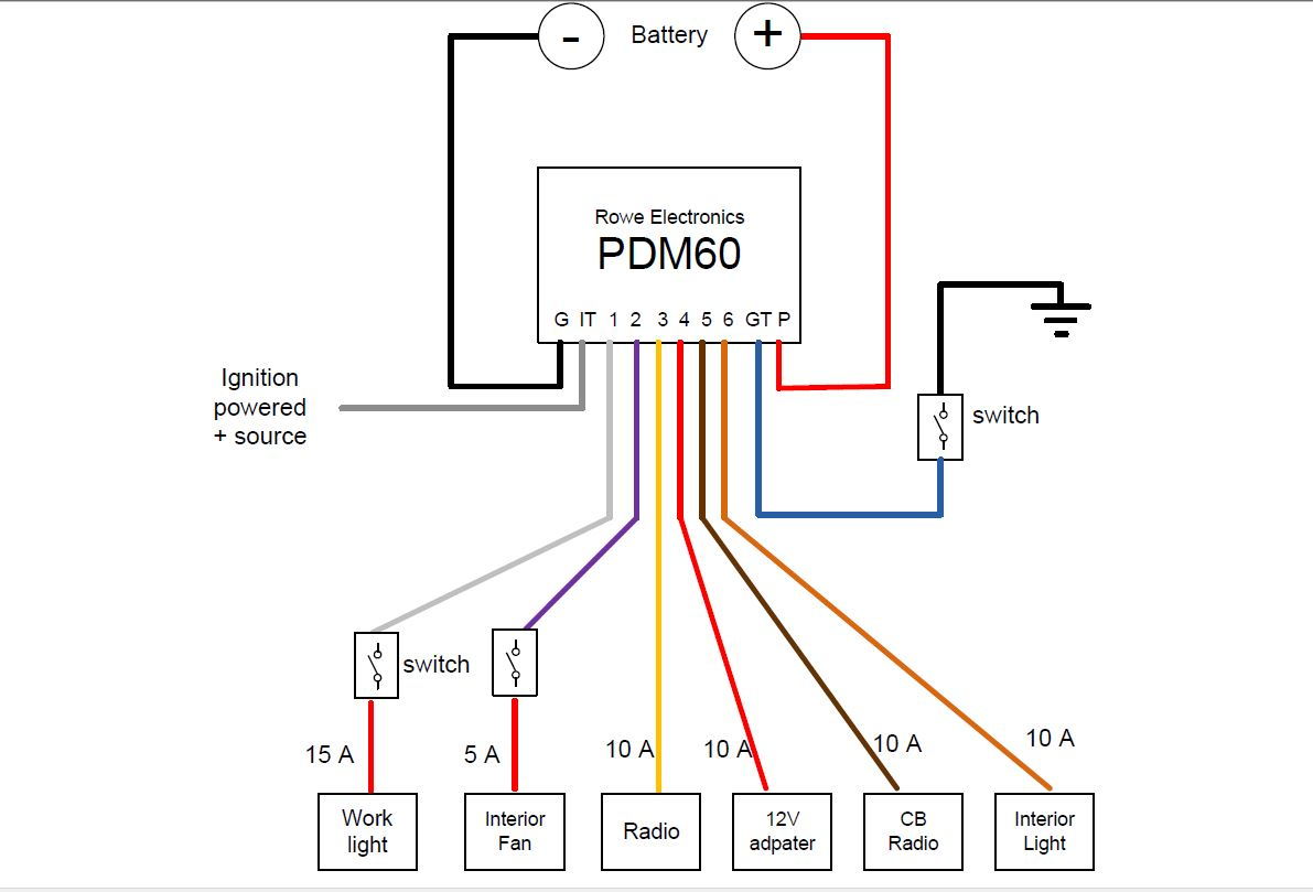
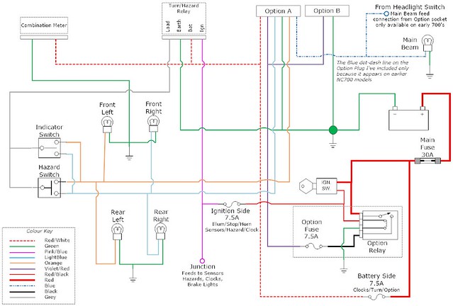
Pdm60 wiring diagram. The pdm60 can be programmed and installed in multiple ways. The io is fully multiplexed using can bus or bluetooth which allows user to simplify wiring designs for ease of installation. If you any more questions regarding the pdm60 we ask that you first contact your dealer. Important to ensure long term hassle free operation make sure that all of your circuit wiring connections are secure insulated to prevent accidental shorting and sealed against the elements. Ignition trigger with start delay in this example all 6 circuits are set to ignition trigger with a 7 second activation delay. The pdm60 comes with a posi lock connector for each circuit and the ground trigger.
You can now program and view the system status on your phone using bluetooth. The pdm60 is fully user programmable via the pdm60 dashboard software set circuit triggeringswitching methods delay circuit activationdeactivation. Built on the strong reputation of the original pdm60 the amplink pdm maintains the total current capacity of 60 amps over 6 outputs. This makes the installation of the pdm60 a breeze and allows for custom fitting the unit to your vehicle. Each output is monitored and will shut down in the event of a short or over current fault. Walking through a wiring diagram to replace the old fuse block on an older honda cb500 café racer with a pdm60 power distribution module.
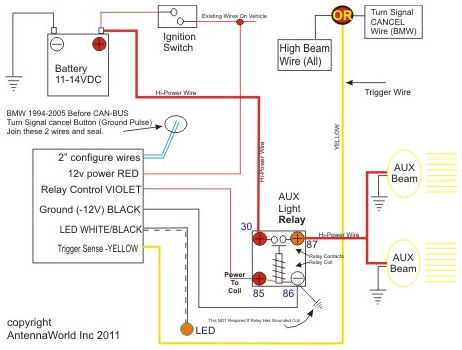
Theres one lead per circuit two trigger wires and the main power and ground leads. Old methods of power distribution have gone the way of the floppy disk. These wire diagrams are intended to help with some of the more common installations. For applications not requiring can bus inputs can be directly wired to the ipdm to trigger an array of outputs. Wiring diagrams are available for you to download. The main power wire is 10ga.
The output wires and ground are all 16ga wire. Theres also a posi tap for connecting the ignition trigger wire. This wire supplies all power to the pdm60. Connect the heavy gauge red power wire directly to your battery positive terminal. With the pdm60 theres no more blown fuses tangled wiring overloaded circuits canbus related power interruptions confusion or frustration. Connect the small black ground wire to the battery negative terminal or ground bus cable that is connected to the battery.
Wiring and troubleshooting will be greatly reduced by installing the ipdm closer to your end device. One wire from the pdm60 to your device. 339 hakes drive norwalk ia 50211 ph. This is the ground wire for the internal circuitry of the pdm60. Also be sure to always connect to a.
Gallery of Pdm60 Wiring Diagram