Correct wiring probably saves an expensive pir sensor from an irrecoverable malfunction and annulment of any warranty terms. If two or more sensors are required to operate all of the lights additional sensors can be connected by extending the nlsle wiring to additional sensors.

How Hc Sr501 Pir Sensor Works Amp How To Interface It With Arduino
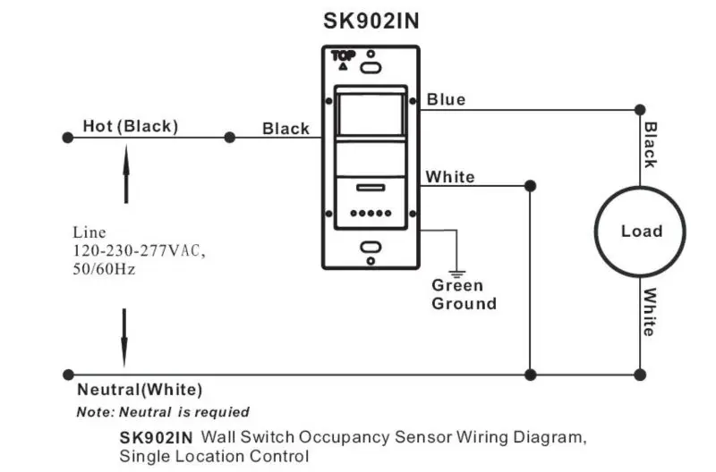
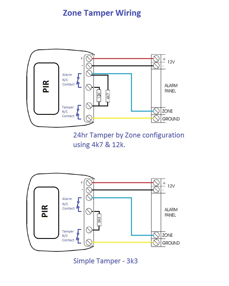
Pir wiring diagram. The diagrams above are for a plastic switch. The image shows a typical pir sensor pinout diagram. Pir wall switch wiring diagram wiring diagram motion sensor wiring diagram. In this video you will see how to wire pir sensor light in the ukit will also show you internal wiring of pir sensor and light. Metal switch or box. Its quite simple to understand the pinouts and one may easily configure them into a working circuit with the help of the following points.
Pir motion sensor light wiring diagram new wiring diagram for a pir motion sensor light wiring diagram wiring diagram consists of many detailed illustrations that display the relationship of varied items. A wiring diagram is a simplified conventional pictorial depiction of an electrical circuit. It reveals the elements of the circuit as streamlined shapes and also the power and also signal connections between the tools. More electrical tips and diagrams wwwaboutelectricitycouk like. It includes guidelines and diagrams for various varieties of wiring techniques and other items like lights home windows and so forth. In addition wiring diagram provides you with the time frame by which the projects are to become finished.
The passive infrared sensor consists of three pins as shown below. This video is a step by step tutorial on how to wire the pir motion sensor. If you want to find the other picture or article about. For both diagrams above one or more lights can be connected to the pir sensor nsl and e terminals. Go through the given diagram of the pir sensor to understand its pin outs and arrangement in the circuit. Pin1 pin2 and pin3 are corresponded to drain source and ground terminal of the device.
Pin 1 is vcc which is connected positive 5v supply. As indicated in the following diagram pin3 of the sensor should be connected to the ground or the negative rail of the supply. Variety of motion sensor light wiring diagram. You will be in a position to know specifically if the tasks ought to be finished which makes it much easier for you to properly manage your time and effort.
Gallery of Pir Wiring Diagram