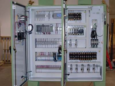
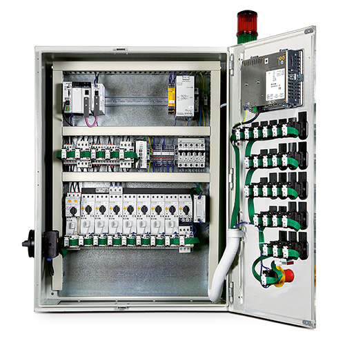
It is a 2 door control panel on the front of which we have some switches that are connected to the plc inputs and outputs. It shows the elements of the circuit as streamlined forms as well as the power as well as signal connections in between the tools.

How To Follow An Electrical Panel Wiring Diagram Realpars
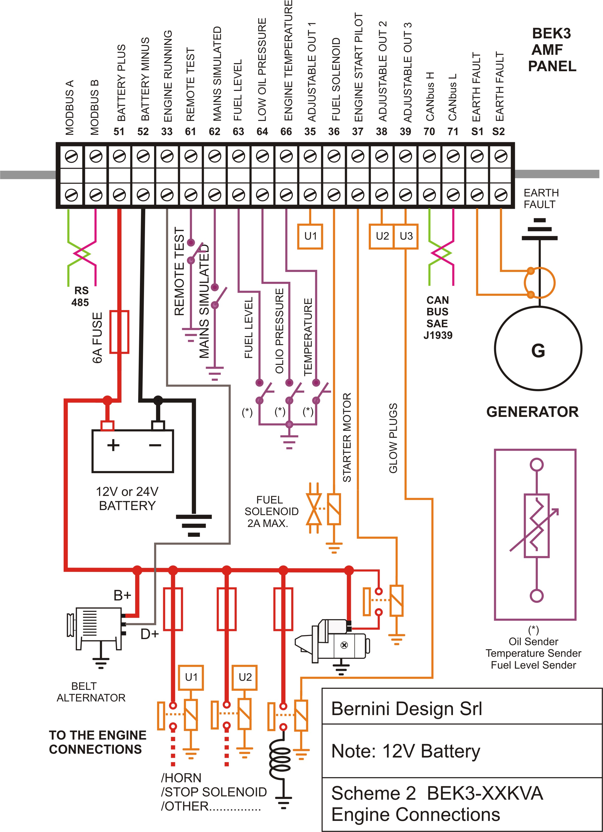
Plc control panel wiring diagram. The following are ten recommended procedures for io wiring. A wiring diagram is a simplified conventional pictorial representation of an electric circuit. So we will understand that how to wire a plc. Wellborn collection of plc control panel wiring diagram pdf. Remove and lock out input power from the controller and io before any plc installation and wiring begins. Apr 7 2017 plc control panel wiring diagram on plc panel wiring diagram.
A wiring diagram is a simplified conventional photographic representation of an electric circuit. Figure 5 below shows a schematic diagram for a plc based motor control system similar to the previous motor control example. Today we will learn about plc wiring in this article we are going to discuss about how to wire a plc or plc wiring. Lets go back and have a look at the control panel and try and figure out some of the connections by following a wiring diagram. How to plc wiring in control panel. Wellborn assortment of plc panel wiring diagram pdf.
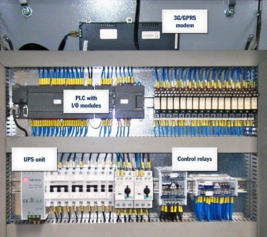
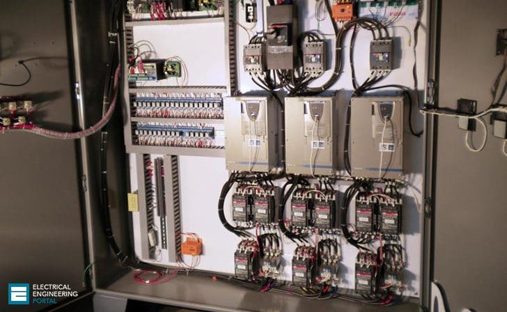
A wiring diagram is a simplified traditional photographic representation of an electrical circuit. Now when we are going to install a plc in any panel or any machine or in any processfirst we have to wire up that. But it does tend to become more complex. As ive mentioned in the previous articles this is a control panel that is used for a system that turns wastewater into clean water. It shows the elements of the circuit as streamlined shapes as well as the power as well as signal connections in between the tools. Get plc control panel wiring diagram pdf download variety of plc control panel wiring diagram pdf.
January 12 2019 by larry a. Overview of the main control panel components now let me give you an overview of all of the important components that we have for this panel and also see how they are connected. Check module type and model number by inspection and on the io wiring diagram. This figure shows the e stop wired to cutoff power to all of the devices in the circuit including the plc. When including a plc in the ladder diagram still remains. Say we have 100 nos of junction boxes installed that means we have 100 nos main cables are there which are coming from field to control room.
Verify that all modules are in the correct slots. April 28 2019 by larry a. It reveals the components of the circuit as streamlined forms and also the power and signal connections in between the gadgets. To avoid these problems we use marshalling cabinet for terminating these 100 nos main cables. So practically it not possible to directly wire these main cables to analog inputoutput cards. In a later article we will get into the details of the wiring diagram and show you how simple it is to read and carry out the wiring on this panel.
Gallery of Plc Control Panel Wiring Diagram