Wiring diagrams for lifan 150cc engine. How to remove a gps disabler from a vehicle.
2014 Nissan Rogue New Version Us Make Relay Nissan Parts Deal
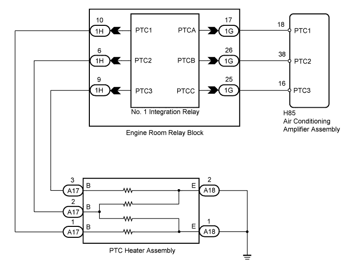
Ptc3 can wiring diagram. Need an off site installation. Where do you get the wiring diagrams. Always use wiring diagram supplied on motor nameplate. Here is a picture gallery about passtime wiring diagram complete with the description of the image please find the image you need. Wiring diagrams for 88 110 125 and 140cc engine. George b il we have.
Wiring capacitors resistors semiconductors table 1 standard elementary diagram symbols contd iron core air core auto iron core air core current dual voltage thermal magnetic single phase 3 phase squirrel cage 2 phase 4 wire wound rotor armature shunt field show 4 loops series field show 3 loops commutating or compensating field show 2. Want to pre load your lot. Choose passtimes sure pass service for certified. Please do not ask for links or softwares. 6 steps pertaining to passtime wiring diagram image size 620 x 465 px and to view image details please click the image. Put that effort on the google search bar.
Hopefully in this video i will show you. Wiring diagrams for lifan 250cc engine. Passtime has excellent reporting so we can identify accounts out for repo which have broken out of a geofence and quickly identify devices that may have been tampered with. Wiring diagrams show components mounted in their general location with connecting wires. A wiring diagram is a simple visual representation of the physical connections and physical layout of an electrical system or circuit. A wiring diagram is used to represent how the circuit generally appears.
Wiring instruction for 70cc 110cc and 125cc with yellow plug. Input current or voltage signal to a 4 20ma dc. Wiring diagrams for lifan 200cc engine. 50cc 150cc moped gy6 wire diagram. Overview technical specification connection diagrams applications d1 ptc3 2 wire current transducer input ac current output dc single accuracy 05 d1 ptv3 2 wire voltage transducer input ac voltage output dc single accuracy 05 operations the transducer converts the ac. Full service gps and starter interrupt device installation no service center.
To help illustrate the differences between wiring diagrams and schematics a basic control circuit will first be explained as a schematic and then shown as a wiring diagram. It shows how the electrical wires are interconnected and can also show where fixtures and components may be connected to the system.
Gallery of Ptc3 Can Wiring Diagram