Westinghouse protective relays this apparatus may. Westinghouse wrf900cs range hood.
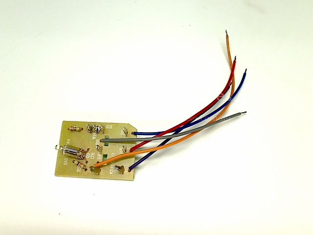
Westinghouse Range Hoods Wrf900cs Switch Box Assembly
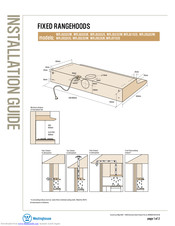
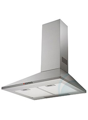
Westinghouse wrf900cs wiring diagram. This westinghouse rangehood is designed for easy maintenance with its smooth stainless steel finish for an effortless wipe down clean. Determine working height mark wall to suit. Wrf900cs wrf900cs canopy rangehood. Kit carbon filter twin 2 pk. The rangehood can recirculate into the kitchen if it is not possible to duct to the exterior. Diagram f fix duct transition to cooker hood body.
Install internal exhaust duct to suit installation type. View download of more than 1859 westinghouse pdf user manuals service manuals operating guides. So if i was to buy this part online then is it just as simple as cutting off the mains power unscrewingcut out wiringremoving the old assembly wire up the new assembly and screw back in. 4 buttons for controlling the operation of the motor position 1 2 3 and turbo ref r. Its a combination of groundbreaking technology and rock solid dependability thats made us one of the worlds most trusted brands. Carbon filters are recommended for recirculation.
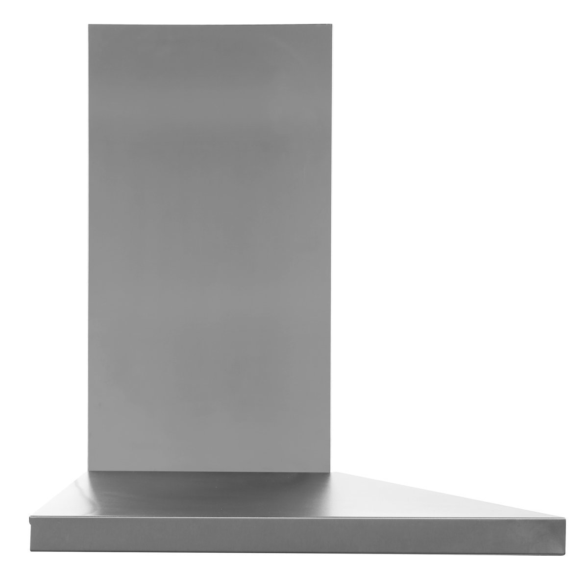
Add to wishlist add to compare. Diagram e e ceiling install cooker hood body. Refrigerator oven user manuals operating guides specifications. For more than a century westinghouse has consistently provided innovative reliable high quality products and customer service. Rangehood fan motor part no. Special price 12500.
The wiring diagram for rear mounting of the adapter is shown in fig. Install cover flue mounting brackets. The panel cutout information necessary for mounting the sleet detector is shown by fig. Westinghouse range hoods wrf900cs complete parts list filter lamp diffuser motor pcb capacitor switch knob handle element repair information exploded. Bigwarehouse westinghouse range hoods wrf900cs appliance spare parts the installation tips on the link above say to note down which wires connect where. Westinghouse wrf900cs.
This unit consists of a potentiometer and pushbutton switch mounted on a small panel itself suitable for. Diagrams g install bottom section of telescopic flu e cover. Four speed control panel this panel is situated on the front of the extractor and includes. H best results are obtained by using a low fan.
Gallery of Westinghouse Wrf900cs Wiring Diagram