Wye delta open transition 3 phase motors. Therell be primary lines that are represented by l1 l2 l3 and so on.
Motor Control Circuits Ladder Logic Electronics Textbook
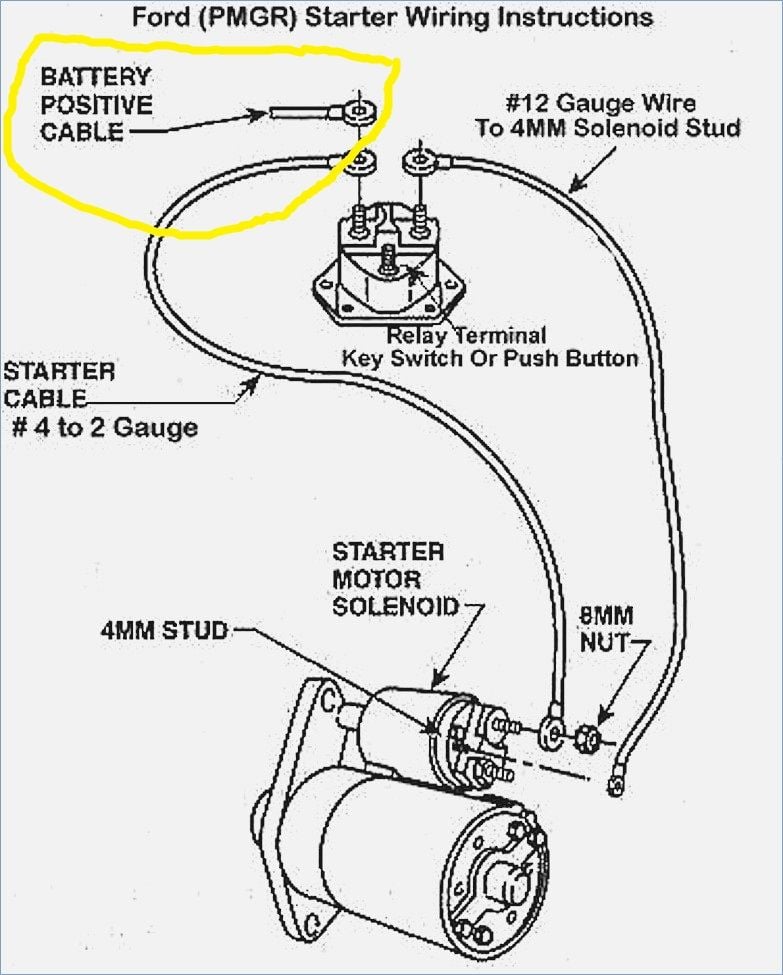
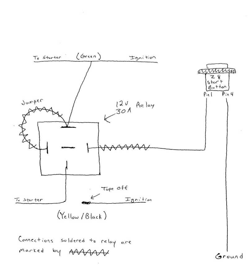
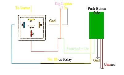
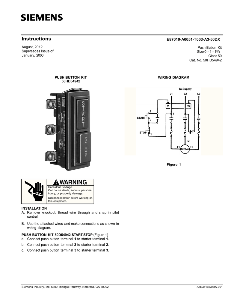
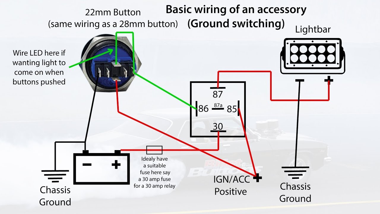
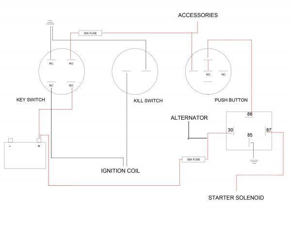
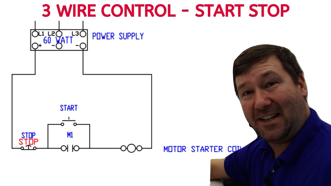
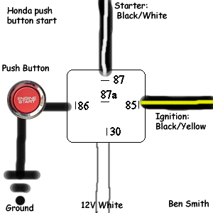
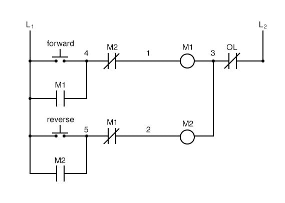
Push button starter wiring diagram. The following diagram is shown for 3 phase motor control of a delta star connection. Injunction of 2 wires is generally indicated by black dot on the junction of two lines. How to completely wire a push button start including battery and starter to your outboard. L2 i c start i i1 i 1 i i lr 0 i. Typical wiring diagrams for push button control stations start stop control wiring diagrams 4 single station maintained contact push buttons t t l1 undervoltage release ol. At times the wires will cross.
It uses three contactors an overload relay one auxiliary contact block a normally open start pushbutton a normally closed stop pushbutton an on delay timer of 0 20 seconds and a power supply with a fuse. But it does not imply link between the wires. L m e 1 the start button mechanically maintains the contacts that take the place of hold in contacts. It contains instructions and diagrams for various kinds of wiring techniques and other things like lights home windows and so forth. Push button starter switch wiring diagram circuit using 11n push button starter switch wiring diagram wiring diagram contains numerous comprehensive illustrations that show the relationship of varied items. As stated earlier the lines at a push button starter switch wiring diagram represents wires.
77 i i i i i i. Push button start craftsman edition duration.
Gallery of Push Button Starter Wiring Diagram