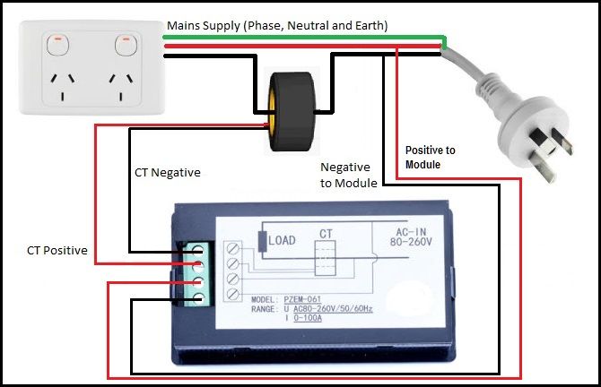
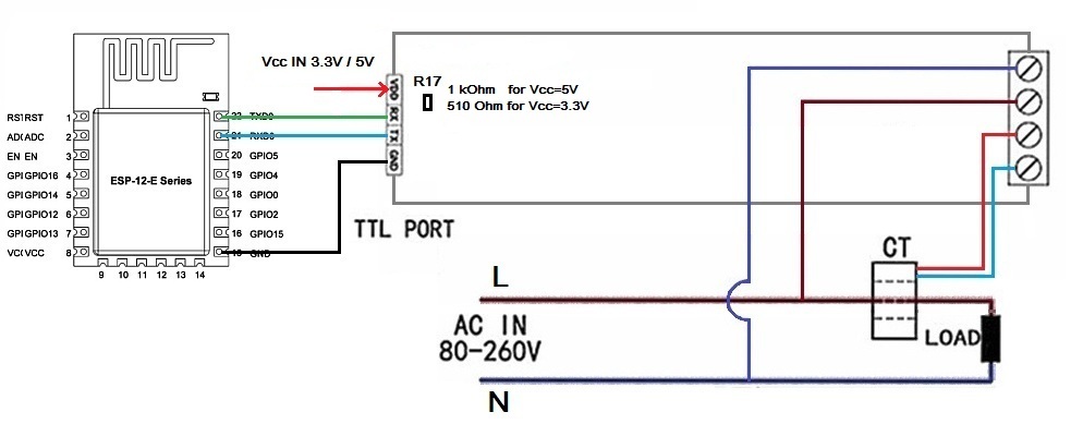
Load can use tl lights bulb led electric drill usb to serial ttl optional for testing functions using the pzem 004t master application. Picture 42 pzem 004t 100a wiring diagram 5 other instructions 51the ttl interface of this module is a passive interface it requires external 5v power supply w hich means when communicating all four ports must be connected 5v rx tx gnd otherwis.

Us 11 03 11 Off 9in1 Dc Combo Meter Battery Monitor Voltage Current Power Capacity Internal Resistance Soc Time Impedance Tester Volt Amp Battery
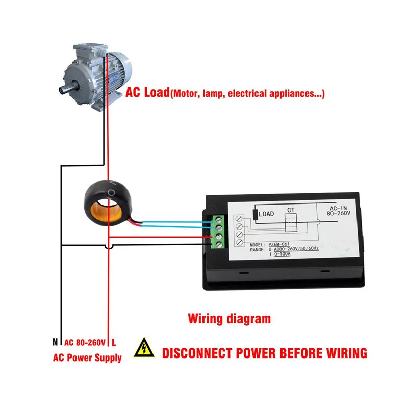
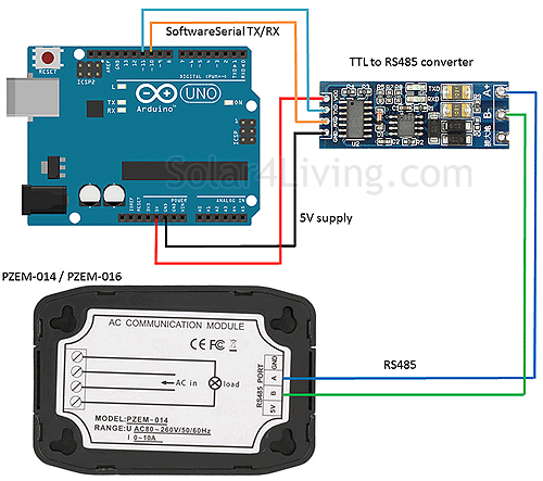
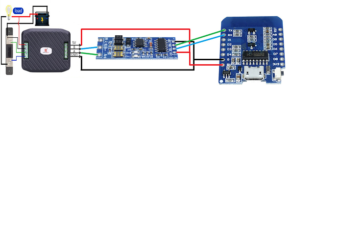
Pzem 015 wiring diagram. According to the actual needs of the clients with different ttl pin board to achieve communicate with different terminals. The voltage and current test input terminal wiring and the serial communication wiring as shown in the figure. Picture 42 pzem 016 wiring diagram 5 other instructions 51 power supply ac voltage provides two isolated outputs after through the switching power supply one way is 33v provides to the measurement system the other way is 5v provides to 485 communication circuits and external circuits. 4 wiring diagram picture 41 pzem 004t 10a wiring diagram. Circuit wiring diagram. Check images below for more information about the 1kohm resistor needed to shift the voltage to 5v from 3v3 for the pzem 004t serial connection.
This new wiring method is suggested by manufacturer to prevent damage. 51 power supply. Wiring diagram the wiring of this module is divided into two parts. First you want to be sure and connect the two wires from the current. Pzem 004t v30 or version 30 is the upgraded version to replace the old pzem004t v10. Picture 41 pzem 014 wiring diagram picture 42 pzem 016 wiring diagram 5 other instructions.
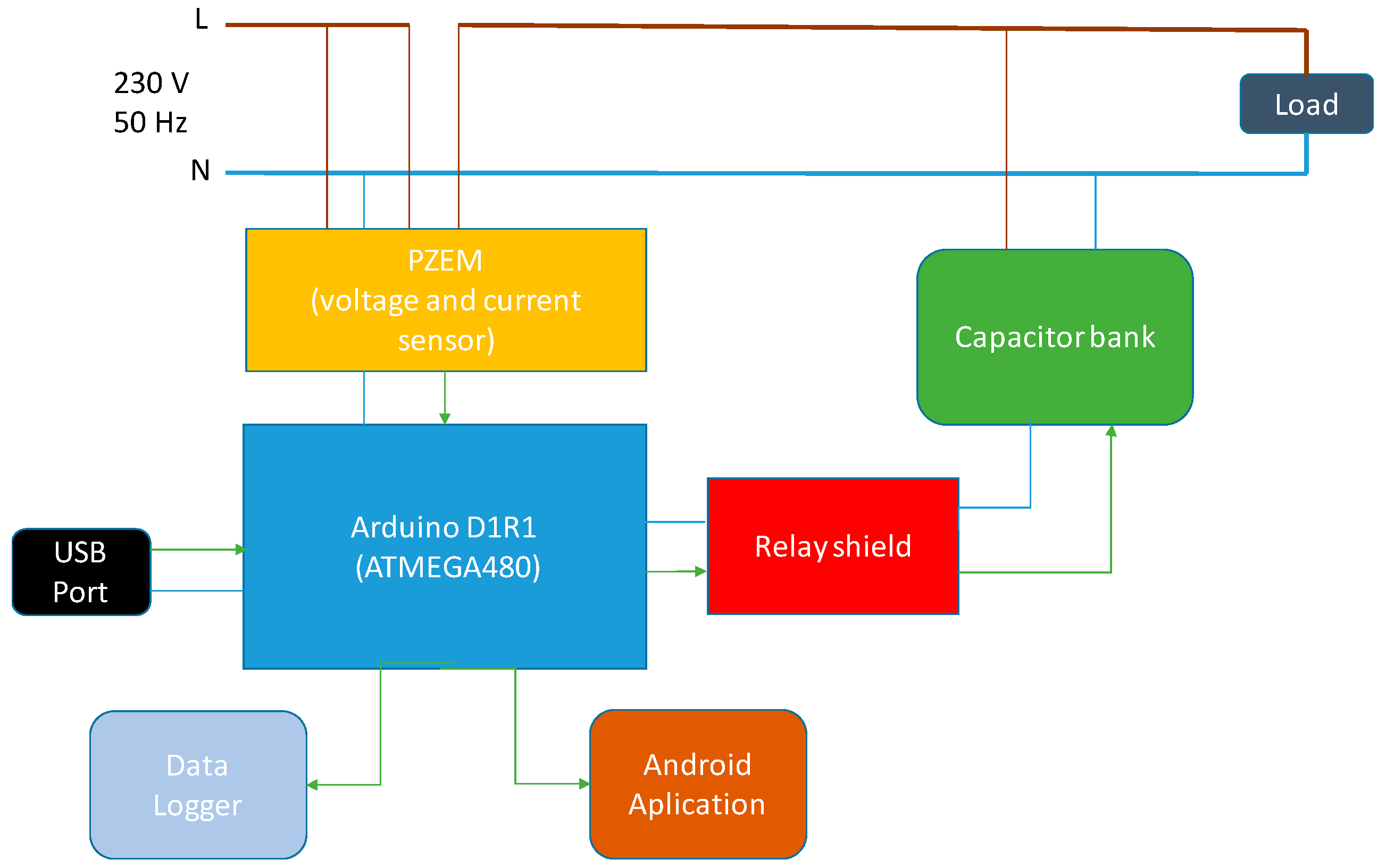
Arrayreviewamountaverage out of 5 5 star 21 1000 4 star 0 00 3 star 0 00 2 star 0 00 1 star 0 00 see all 21 reviews. The updated versionof pzem004t is best for the purpose of the diy project where we need to measure the voltage current power energy frequency power factor frequency and pf is extra added in the new versionusing. Arduino uno or arduino mega2560. Ac voltage provides two isolated outputs after through the switching power supply one way is 33v provides to the measurement system the other way is 5v provides to 485 communication circuits and external circuits. The black cable between meter and shunt is wired differently with it is in the diagram on the back of meter. Pzem 015 battery tester dc voltage current power capacity internal and external resistance residual electricity meter with 100a shunt cod.
How to wire up a peacefair pzem 061 ac panel meter. There are two pair of wires to connect the panel meter to your load. Some m f f f jumper cables. Calibration per theo as the pzem is a dedicated energy monitor device calibration in tasmota is currently not supported. 6 answered questions. In this example pzem 004t v3 module program some hardware is needed among others.
The old version has been sold out in most of the online store and no produce anymore.
Gallery of Pzem 015 Wiring Diagram