520 to 21700 lbf in. Connect according to the enclosed wiring diagram or if the actuator is of standard design according to the wiring diagram below.

Rcel005 Rcel Pdf Free Download
Rcel 015 actuator wiring diagram. By using this site you agree to the usage of cookies. Cpt built into the actuator. Rcel instruction no 438b electric actuators 015250 installation 1. Spring return version available. Check that the cable entries and possible blind plug are sealed. Switches rcel 15 thru rcel 250 remote control inc.
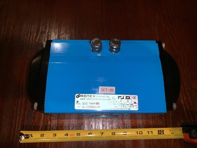
Rcel light industrial worm drive torque output. Test run the actuator and check that the limit switches work correctly. All actuators have a rugged ip67 aluminium housing and are fitted with 4 limit switches anti condensation heater and manual override. Single and three phase and dc options available in a wide range of supply voltages. Mechanical limit stops designed to prevent over travel of quarter turn applications. Manual override heater standard.
The wiring diagram is drawn in unaffected position the valve in interme diate position. Easily calibrated with buttons on the pcu dhc 100d. Voltage or current output can be adjusted to optional range within 0 10 v dc with steps of 00016 v or within 0 20 ma with steps. The wiring diagram is drawn in unaffected position the valve in intermediate position. For further information please refer to our privacy policyprivacy policy. Not for eex actuators.
Adjustment see instruction c. Only electric wiring acc. Close we use cookies in order to optimise this website and for continuous improvement. Tes t run the actuator from the intermediate position checking that the actuator turns in the correct direction. Hq004 hq006 single phase wiring diagram. Test run the actuator from the intermediate position checking that the actuator turns in the correct direction.
Electric wiring see instruction b. Output torques of 40 to 3000nm. Torque switch is cam actuated and factory set to provide over torque protection for valves available in size rcel 15 thru rcel 250. Hq004 hq006 24vac wiring diagram. Position control unit for rcel 006 250. Rcel 015 250 installation maintenance manual.
Manual operation see instruction d. Mounting on valve see instruction a. To instruction b is required when the actuator is delivered from remote control mounted on. Hq004 hq006 24vdc wiring diagram. Cam actuated end of travel limit switches are easily adjusted to de energize actuator for precise valve position. Csa cus class 1 div 1 group c d exp approvals 120v only.
Rotork wiring diagram selector.
Gallery of Rcel 015 Actuator Wiring Diagram