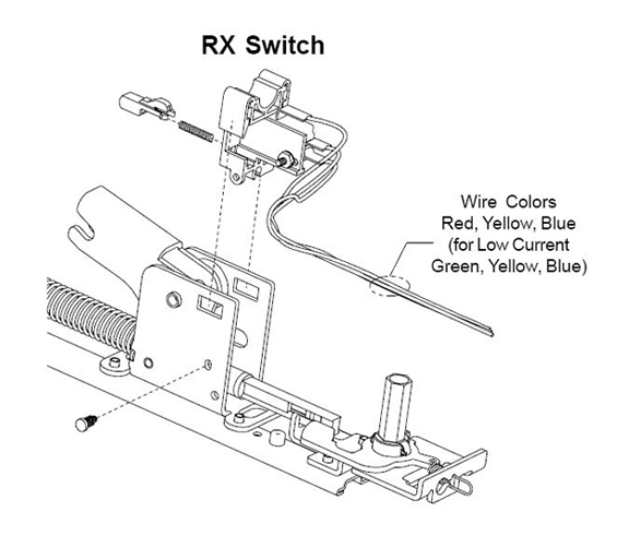
How to connect a request to exit button in a kisi stand alone setup. Push to exit button wiring diagram.

Vis 7001 Indoor Outdoor Weather Waterproof Rated Ip65
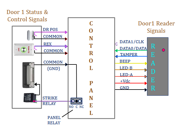
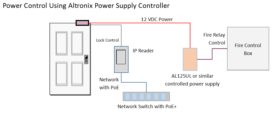
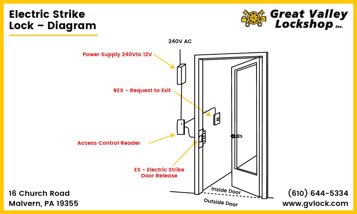
Request to exit button wiring diagram. Essex electronics stainless steel vandal resistant request to exit buttons can be used to control an automatic door electric lockstrike magnetic lock or any electrically controlled device. Wired in series power supply for fail safe strikes and magnetic locks should be dc. How to wire a magnetic lock with backup battery exit button and key switch. Mower wire diagram online wiring diagram the contacts are ul listed with 10 amp capacity. Single door controlled egress wiring diagram 01 single door digital entry wiring diagram 10 single door dk 26 with door prop alarm wiring diagram 15 single door dk1 11 xms dt 7 wiring diagram 20 single door dk 26 remote release wiring diagram 14 single door dk 26 unl 24 and dt 7 wiring diagram 18 single door dk 26 using the hard code to toggle lock off and on wiring diagram. When installing kisi as a stand alone product on a fail safe lock it is important to understand how to wire necessary non kisi components to the setup.
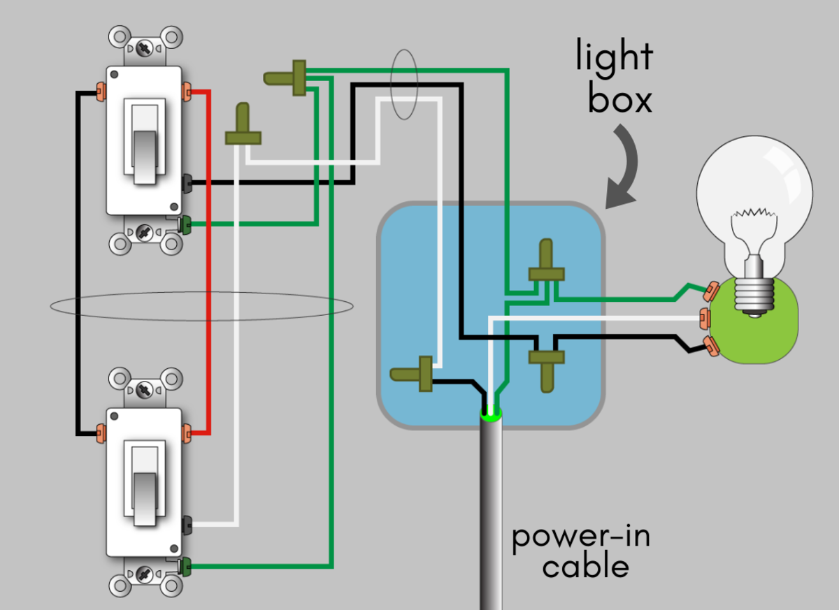
Run four wires through the wall to a single gang or slimline back box. Screw the plate into the back box taking care not to crimp the. No touch request to exit sensor seco larm usa inc 3 wiring diagram. Wiring instructions magnetic lock or fail safe strike with button keypad maintained button and remote receiver. Connect the four wires from the back box to the request to exit sensor according the wiring diagram above. This and other diagram and tutorials are available on our website at.
If this is not available you may use an ac power source and wire inline a full wave bridge rectifier. This guide specifically will explain the wiring of a request to exit rex button. This will conver t the ac to dc.
Gallery of Request To Exit Button Wiring Diagram