Rosemount 3051 pdf user manuals. Rosemount 54 e discontinued rosemount 6081 transmitter discontinued.

Rosemount Transmitter Wiring
Rosemount 3051 wiring diagram. 5 connect the wiring and power up. The rosemount 3051 wiring diagram material as well as style of this electrical wiring representation actually will touch your heart. Figure 5 1 shows wiring connections necessary to power a rosemount 3051 and enable communications with a handheld communicator. Use the following steps to wire the transmitter. Remove the housing cover on the field terminals side. Block diagram for the model 3051 transmitter withfoundation fieldbus pressure 3051 305101b input lcd block display.
We present rosemount 3051 wiring diagram below due to the fact that it will certainly be so easy for you to access the net solution. You can locate more and more experience and knowledge how the life is gone through. Rosemount 3051 pressure transmitter with the rosemount 3051 pressure transmitter youll gain more control over your plant. The rosemount model 3051 transmitter is among the worlds first devices to be. Rosemount 5081 explosion proof transmitter. 41 ground signal wiring.
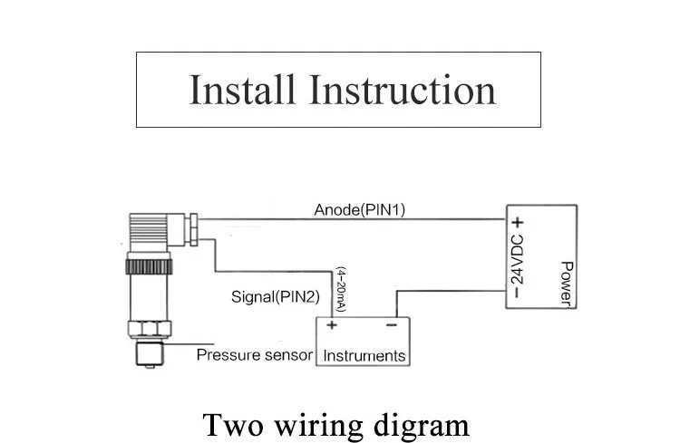
Do not run signal wiring in conduit or open trays with power wiring or near. Wiring diagram for rosemount 3051s ers system with remote display in daisy chain configuration. Interconnecting wire routes may be shown approximately where particular receptacles or fixtures must be upon a common circuit. Rosemount 3051 foundation manual architectural wiring diagrams show the approximate locations and interconnections of receptacles lighting and enduring electrical facilities in a building. Connect the positive lead to the terminal pwrcomm and the. Power supply note installation of the transient protection terminal block does not provide transient protection unless the rosemount 3051s case is properly grounded.
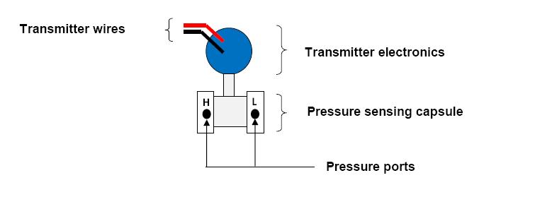
The sections are organized as follows. Rosemount liquid analysis wiring diagrams rosemount 105656 intelligent four wire transmitter. Rosemount 1066 single channel transmitter. Transmitter wiring junction box housing a b. Flexible wiring topology apply a multi drop tree or combination configuration. Youll be able to reduce product variation and complexity as well as your total cost of ownership by leveraging one device across a number of pressure level and flow applications.
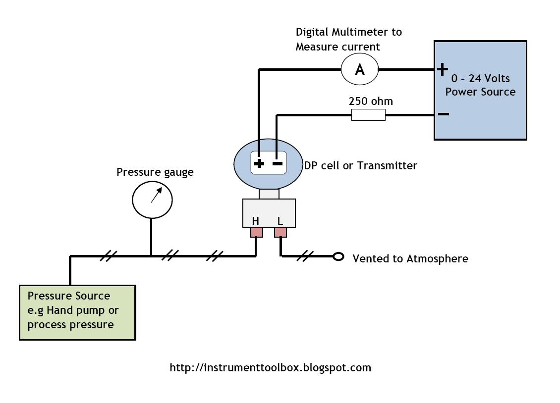
Page 12 august 2016 quick start guide 55 shield grounding connect the shield from the rosemount 3051s ers communication cable assembly to each housing case as shown for the applicable wiring configuration in figure figure 11. Rl 250 ω b. Rosemount 1057 triple channel transmitter. View online or download rosemount 3051 quick start manual quick installation manual.
Gallery of Rosemount 3051 Wiring Diagram