6 the special design of the tachometer base allows for a variety of mounting possibilities. A wiring diagram is commonly made use of to fix problems as well as to earn sure that all the connections have been made which every little thing exists.

Smiths Tachometer Servicing How To Library The Morgan
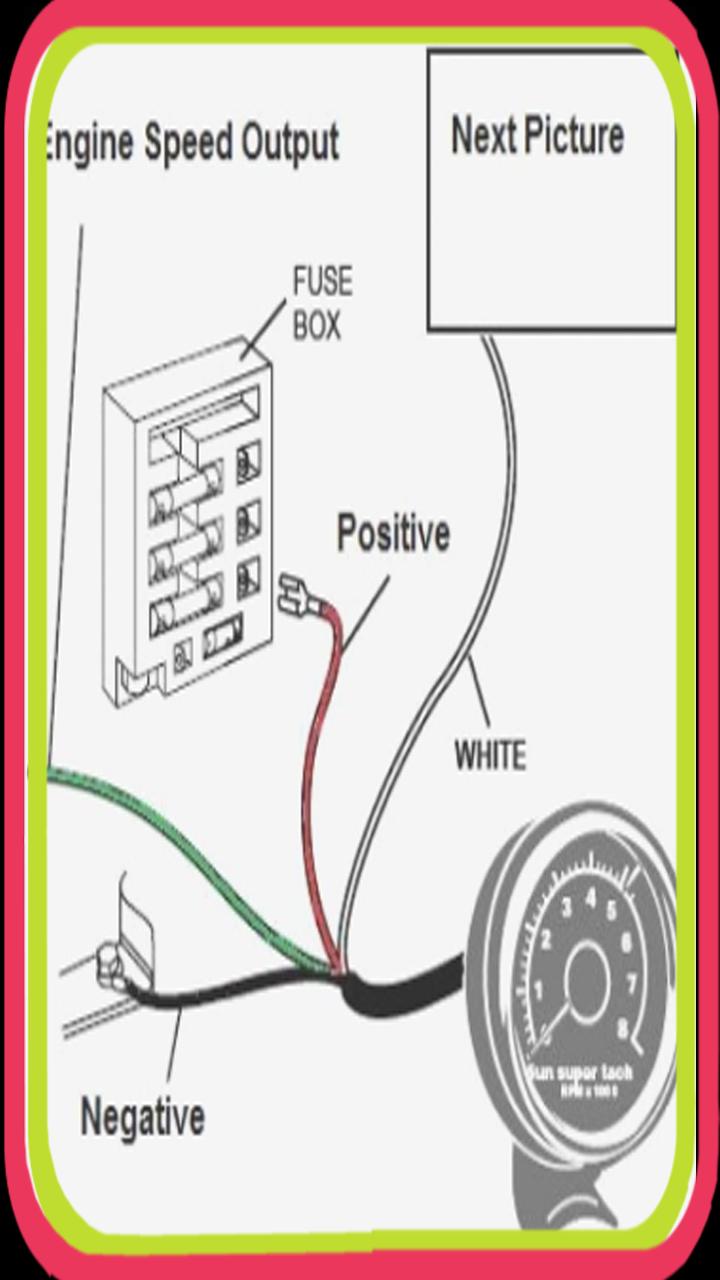
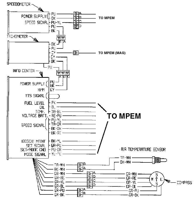
Rpm gauge wiring diagram. Locate the 12 volt switched dash lighting supply for the dashboard on the car fuse box. Wire cutters wire strippers automotive diagnostic tool used for finding tachometer wire ratchet and sockets screwdriver drill. Ignition switch to 12 volt positive. At the top left of the diagram we see the cylinder selector switch. Existing holes will have a rubber grommet to protect the wiring. Circuit diagram of generation one and two smiths tachometer as used tachometer wiring excerpt of gt diagram tach wiring is.
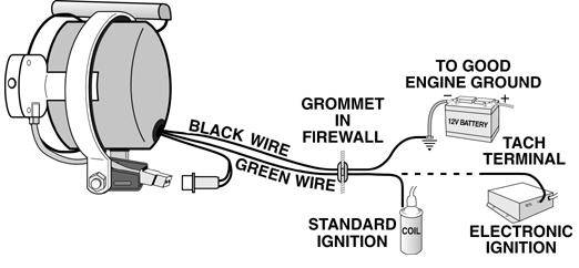
1996 evinrude 40hp parts used in this test. Shorting or stop circuit. Wire to a junction and attach the wire from pin 4 at this junction ie. Use an existing hole in the firewall to pass the black and green wires through to the engine bay. The tachometer is configured at the factory for 4 ppr. Beginning with the tachometer fig.
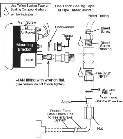
Cut out a notch in this grommet to pass the wires through or drill a new hole for the wires to be sent. Attach the base using screws provided or use a pop rivet tool. Attach the tachometer backlighting wire. A photographic diagram would show more detail of the physical appearance whereas a wiring diagram makes use of an extra symbolic notation to emphasize interconnections over physical look. Temperature switch to warning horn andor. Make sure this switch is set to the number of cylinders for your engine.
Attach the wire from pin 3 to a ground negative source. Tachometer can be purchased from most any auto parts store for as low as 33. 1 3 4 1 8 note. Installation images shown may be different from your actual model. Connect a wire from pin 5 to a constant 12 or 24 volt source. Mine was salvaged from my old truck 3m quick splice connectors 14 18 gauge 410 walmart tools.
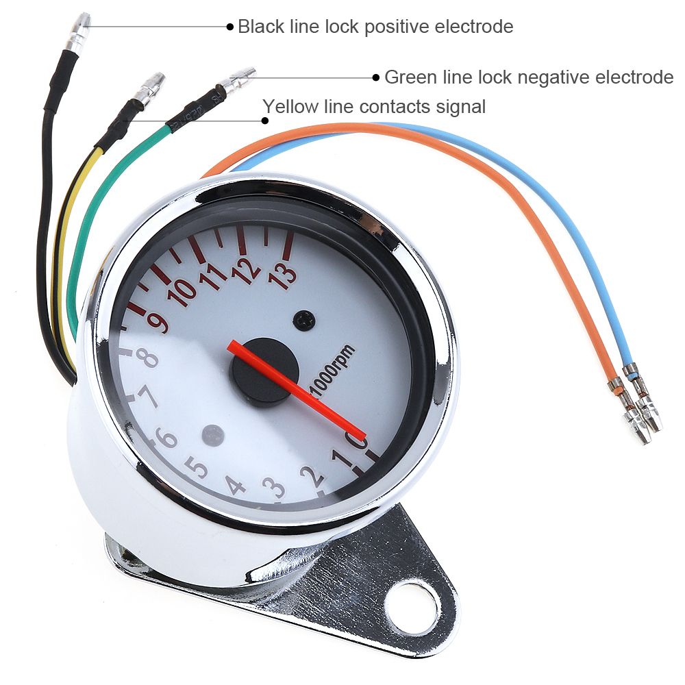
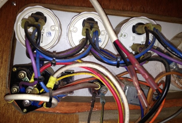
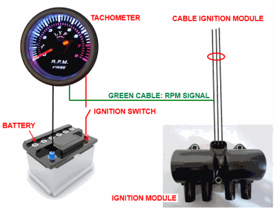
With the tachometer and wiring in place finishing the job is easy. 1 here shows the back of a typical gauge. One such source can always be found where the battery is attached to the metal frame of the vehicle. Un fused wire from battery. Black yellow stripe. The wiring basics of connecting a tachometer rpm gauge to an outboard motor.
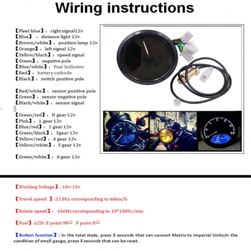
Outboard motor control wiring part 1. Provide power to the tachometer backlighting. Outboard engine wiring series links. Protected fused wire from battery andor protected 12 volt to trim panel control. Refer to diagram d. Most vendors will use one tachometer head to cover a variety of engines.
By way of a loop of wire in series with the ignition coil attached to the rear of the case. Fuel sender to gauge. Red purple stripe. Apply power to the tachometer by attaching the power input wire of the tachometer to the 12 volt dashboard lighting supply of the car.
Gallery of Rpm Gauge Wiring Diagram