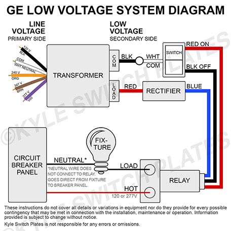
The relay employs a split low voltage coil to move the line voltage contact armature to the on or off latched position. Included for free with the purchase of any ge low voltage lighting component.

5628e4a Flasher Wiring Diagram 5 Pin Wiring Library
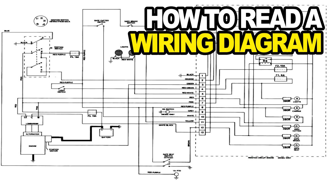
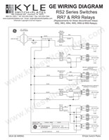
Rr7 relay wiring diagram. New ge rr7 maintained relay switch comes equipped with 3 low voltage leads and is the best replacement option for discontinued ge relays for standard unlighted switches. One copy per purchase. Reaction coordinate diagram endothermic. Please right click on the image and save the illustration. Audison vcra wiring diagram. Wire sizes all low voltage wiring within cabinet.
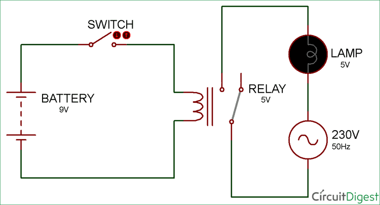
146 0041 03c next to blue wires of rr7 or rr8 relays. Ge model rr 7 and rr 9 lighting relays are mechanical latching type units requiring only momentary 24 vac switch circuit pulses to open or close line voltage circuits. C5 corvette shifter indicator wiring diagram. The on coil moves the armature to the on position when a 24 vac control signal is impressed across its leads251rr9 relay wiring diagram. All ge low voltage relays may be used to full rated capacity for tungsten filament ballast or resistive loads. 18 awg minimum between cabinets caution do not connect more than one rr relay coil to any sequenced numbered terminal.
Eager beaver 20 chainsaw parts diagram. Our people also have some more images linked to low voltage lighting relay wiring diagram please see the. Msd multiple spark discharge wiring diagram. Ge rr8 relay wiring diagram from ge rr7 wiring diagram sourceengine39robertsbullsnl ge rr8 wiring diagram wiring diagram split from ge rr7 wiring diagram source5asdeumeventsolutionde ge rr8 wiring diagram wiring diagram split from ge rr7 wiring diagram source5asdeumeventsolutionde. Connect power supply ground wire to the hole in tub using green 8 32 screw figure 3. Rr7 relay wiring diagram rr7 ge relay wiring diagram of a picture i get directly from the low voltage lighting relay wiring diagram collection.
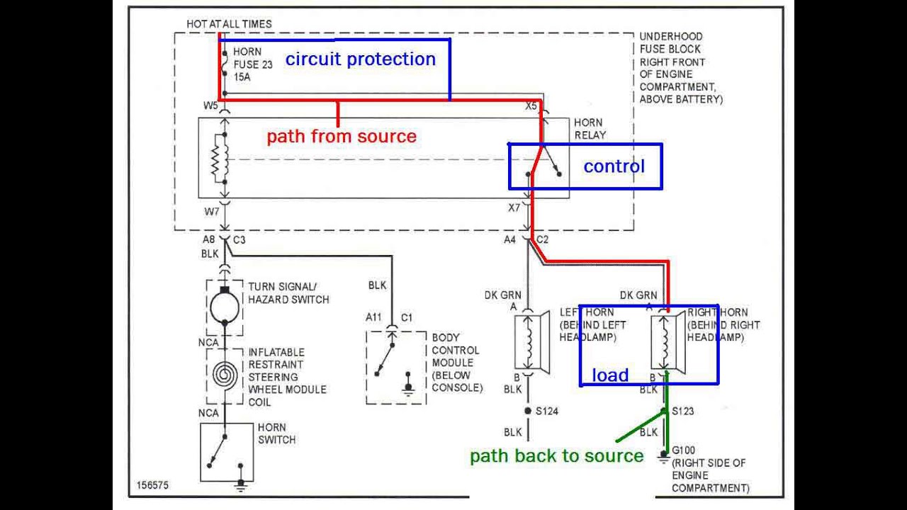
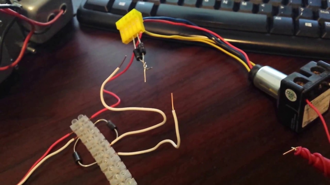
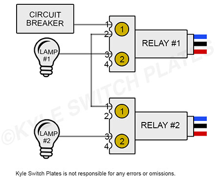
You can save this photographic file to your personal device. 22 awg minimum except 18 awg minimum on 24 vac as shown. Read this kyle switch plates exclusive instructions for installing newer ge rs2 series low voltage switches in remote control wiring systems using rr7 rr8 or rr9 mechanical relays and rt series transformers. Wire from the circuit breaker through each relays spst output terminals and from there to the loads. Master switch control of rr7 standard 3 wire relay with stripped leads. These switch control relays are also a compatible replacement for standard sierra electric and bryant brand solenoid relays and have a split low voltage 24v coil to move the.
Wire line voltage the load circuits are shorted. Make sure that all line and low voltage wiring is confined to the appropriate areas. This is the diagrams. Low voltage between cabinets. For private use only no sharing or. The model rr 9 includes an auxiliary contact on the low voltage side for status indication.
Rr7 relay wiring diagram.
Gallery of Rr7 Relay Wiring Diagram


.png)