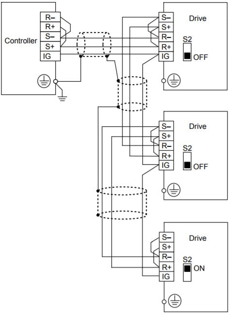
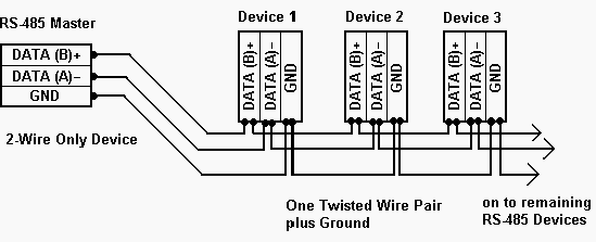
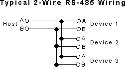
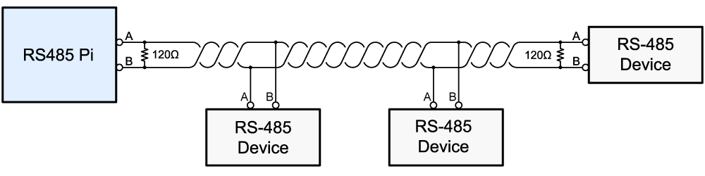
It reveals the parts of the circuit as simplified shapes and the power as well as signal links in between the gadgets. Wiring rs 485 networks daisy chain topology in practice the wiring of a daisy chain topology is most easily implemented by using the rs 485 connector on the device to link the network to the upstream and downstream nodes.
Bacnet Modbus Rs 485 Apogee And Metasys Wiring
Rs 485 wiring diagram. To transmit a logic 0 line b is low and line a is high. The ekey home. A twisted pair is ideal for rs485 cable since the twisting make both wires and exposed to an identical noise figure thus canceling the noise itself when received at the interface port. The txd and txd lines carry transmit data while the rxd and rxd contain the receive data. It shows the components of the circuit as simplified shapes and the knack and signal connections amongst the devices. A wiring diagram is a streamlined traditional pictorial representation of an electric circuit.
Activation should be carried out by a knx specialist. But it does give some guidelines. Activation notice extensive specialist knowledge is needed to configure a knx system. This could lead to incorrect wiring so care should be taken to avoid inadvertently connecting. These guidelines and sound engineering practices are. Proper wiring for rs 485.
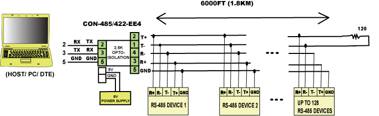
The distances these signals are carried is greater due to differential signals. Two wires are required for each signal. If you wish to transmit four signals then eight wires are needed. Rs 485 eiatia 485 differential data transmission system basics. This application note is intended to provide basic guidelines for wiring an rs 485 network. Environment rs485 serial modbus communications.
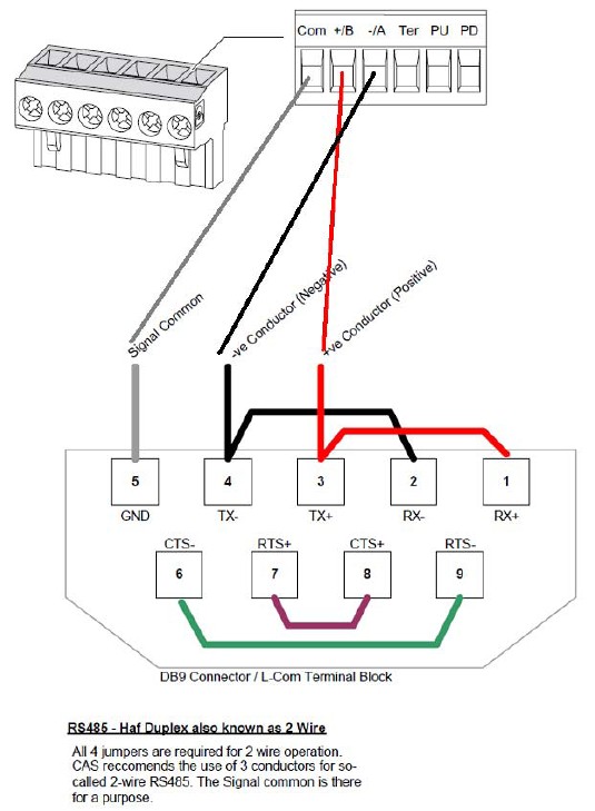
To transmit a logic 1 line b is high and line a is low. Figure 3 is an rs485 wiring diagram for rs485 pinout db9 connectors. Rs485 wiring diagram stylish rs485 wiring diagram sparkling rs485 wiring diagram high quality rs 485 changed into add at november 19 2017 at foursixteen pm by way of friedhelmzimmer and this rs485 wiring diagram elegant rs485 wiring diagram fresh rs485 wiring diagram amazing rs 485 wallpaper has viewed by using users. The figure below shows a single rs485 rs422 signal being transmitted. The wiring diagram displays the wiring of the ekey home converter knx rs 485. Rs485 and rs422 drive lines in a differential fashion.
Variety of rs485 wiring diagram. This document attempts to explain correct methods of wiring rs485 communication networks in industrial environments based on various application notes and technical articles. Refer to the wiring diagram for the finger scanner for the wiring of the ekey home finger scanner and the lock. Rs485 4 wire wiring diagram wiring diagram is a simplified up to standard pictorial representation of an electrical circuit. Figure 4 is a pin diagram for both 25 pin rs485 pinout half duplex and full duplex pinout connectors. The rs 485 specification officially called tiaeia 485 a does not specifically spell out how an rs 485 network should be wired.
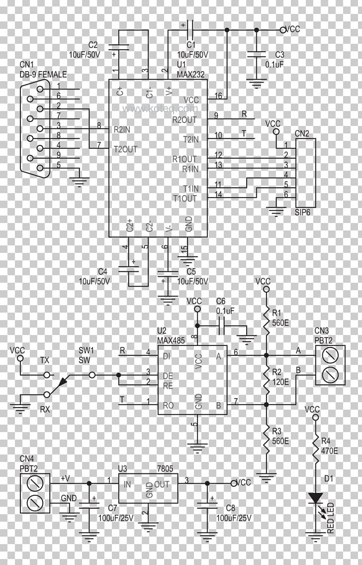
The rs232 rs485 adapter circuit diagram is show below rs232 db9 is used as the rs232 port while only a terminal block is used as rs485 connector.
Gallery of Rs 485 Wiring Diagram