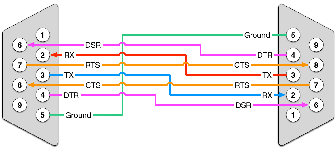
Rs232 db25 pc loopback test plug connecting together two serial devices involves connecting the rx of one device to the tx of the other and vice versa. The majority of them use usb cable.
Rs232 Serial Cable Pinout Information Lammert Bies
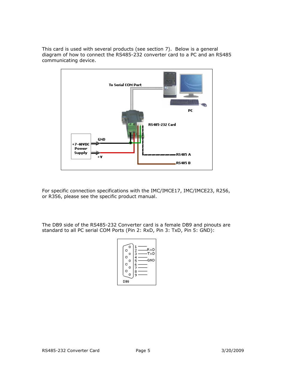
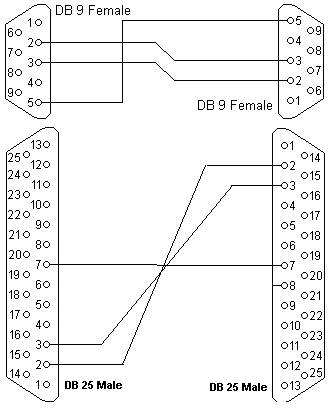
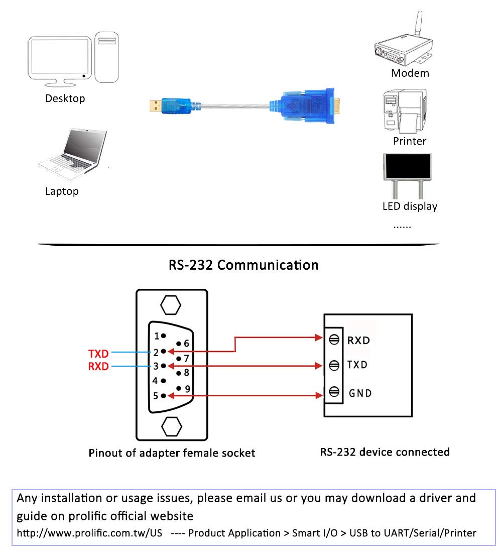
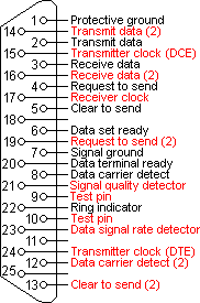
Rs232 wiring diagram. Even the most tempestuous software that insists on using all of the rs232 pinout can surprisingly be short circuited. Pin connections db9 9 way db25 25 way. Rs 232 standardstia 232 are defined by tia telecommunications industry association. Rs 232 defines both the physical and electrical characteristics of the interface. Rs 232 is practically identical to itu v24 signal description and names and v28 electrical. Then the rs232 wiring was condensed into the 9 pin connector a victim of evolution if you like.
Black cable serves as floor just like in any other device. Rs232 is an active low voltage driven. Rs 232 cables wiring and pinouts. In addition it can link device to a power supply for charging purpose. Typically it uses black green red and white cable colors. Rs232 serial port monitoring hardware stands out for a number of reasons including its 9 pin rs232 pinout.
A twisted pair is ideal for rs485 cable since the twisting make both wires and exposed to an identical noise figure thus canceling the noise itself when received at the interface port. D0 cbl rs 232 rj12 to rj12 shielded cable wiring diagram. The cable may be utilized to transfer data from one apparatus to another. Use a cable wired as shown in the diagrams below. The red one is for sure cable with dc ability of 5 liter. Usb to rs232 wiring diagram usb to rs232 circuit diagram usb to rs232 wiring diagram there are lots of kinds of electronics available.
Wiring and constructional details for rs232 serial data cables. However wireless designer can connect to a receiver frame over a pcs rs232 port as well. This pinout can make a world of difference for successful rs232 serial communications. Dr receiver has db9 connector on rear panel venue receiver has 35mm trs jack on rear panel. Thus it is important to understand how the 9 pin rs232 cable pinout can affect the flow of serial data between devices. The rs232 rs485 adapter circuit diagram is show below rs232 db9 is used as the rs232 port while only a terminal block is used as rs485 connector.
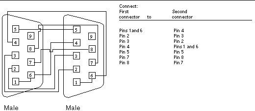
According to usb rs232 cable wiring diagram there are only four wires used from the cable. Rs232 cable wiring diagrams normally the rs232 port is used by touch panel controllers and similar devices. The diagram below indicates how you would go about connecting two pcs together without handshaking. There are oodles of different types of rs232 cables but the only real difference is which pins of the rs232 port they actually use. D2 250 to d2 240 communications wiring using rs 232.
Gallery of Rs232 Wiring Diagram