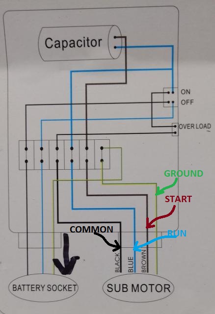
The previous home owner had buried the cable under ground and the over the years the cable deteriorated and corroded and eventually shorted out. The diagram below references a v pump and wiring.

Float Switch Installation Wiring Amp Control Diagrams Apg
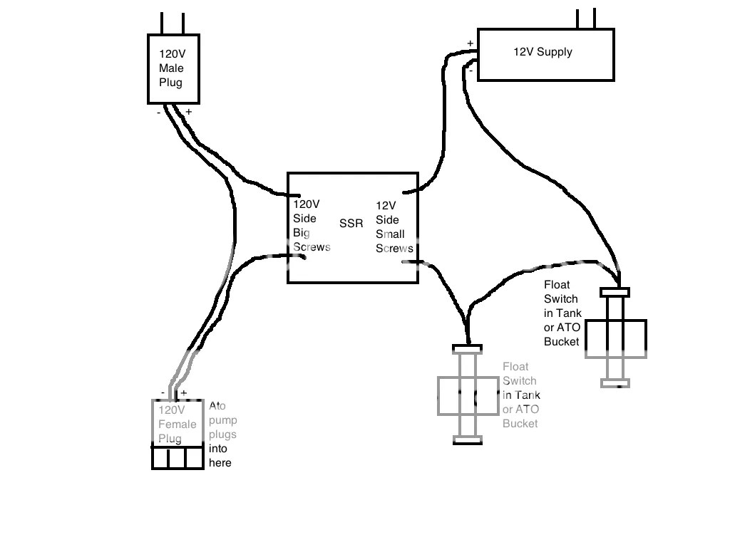
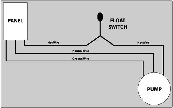
Septic pump wiring diagram. A wiring diagram is a simplified traditional photographic representation of an electric circuit. Assortment of septic pump wiring diagram. I recently re wired a receptacle for the lift pump for my septic system. Inside the septic tank a float switch tethered to a fixed position in the tank floats up and down with the liquid level. Septic pump wiring diagram. The other leg will connect to the hot wire from the pump.
The ground wire from the panel will connect directly to the ground wire from the pump. I need a wiring diagram for an clearstream wastewater aerobic septic system answered by a verified electrician. A wiring diagram is a streamlined conventional photographic depiction of an electrical circuit. The float switch has two legs. Septic system lift pump and the float switch electrical question. Assortment of septic pump float switch wiring diagram.
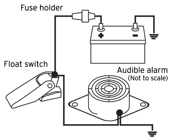
It shows the parts of the circuit as simplified forms and also the power and also signal links between the devices. Over 95 of aerobic septic systems use v rather than v. The neutral wire from the panel will connect directly to the neutral wire from the pump. Septic system alarms alert the homeowner when an imminent sewage back up is likely. Now you are left with the hot wire from the panel and the hot wire from the pump. When the liquid level gets too high a switch inside the float closes the alarm circuit activating the alarm.
Septic pump float switch wiring diagram. One leg of the float switch will connect to the hot wire from the panel. It shows the components of the circuit as simplified shapes as well as the power as well as signal links between the tools. Septic alarms alert homeowners of septic system problems.
Gallery of Septic Pump Wiring Diagram