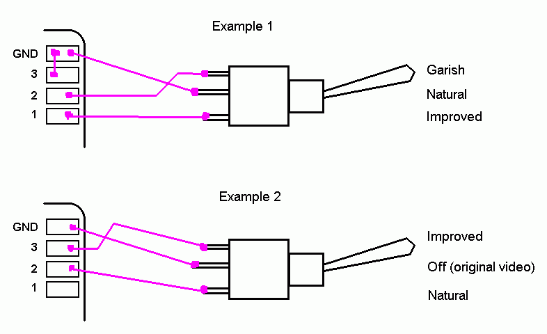
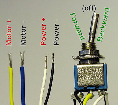
I recently ran into a wiring problem and made an illustrated post on how i figured out the solution and some guesses as to why i came to the solution i did. Here is a diagram of a spdt toggle switch.

2 Toggle Switch Wiring Diagram Suzukif1 2004 Rmnddesign Nl
Spdt toggle switch wiring diagram. Literally a circuit is the path that enables power to circulation. One of the most common pieces of circuit bending hardware is the single position dual throw spdt switch. The switch is always making one of the two connections and flips between them. Variety of spdt toggle switch wiring diagram. A wiring diagram generally provides info about the family member position as well as setup of gadgets as well as terminals on the devices in order. It shows the elements of the circuit as simplified forms and also the power and also signal links between the tools.
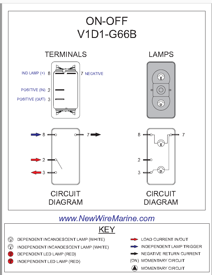
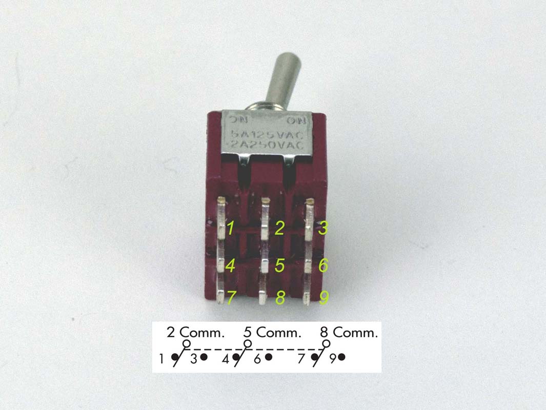
We will now go over the wiring diagram of a spdt toggle switch. Terminal 2 is connected to power. Dp switches control two independent circuits and act like two identical switches that are mechanically linked. Sp switches control only one electrical circuit. A wiring diagram is a streamlined standard photographic depiction of an electrical circuit. Below is the schematic diagram of the wiring for connecting a spdt toggle switch.
Here is a diagram of a spdt toggle switch. Sp and dp refer to single pole and double pole st and dt refer to single throw and double throw. Pole refers to the number of circuits controlled by the switch. 2 methods are explained with associated wiring diagrams. Hallway and corridor wiring circuit diagram using two way switches. Spdt toggle switch wiring diagram a newbie s guide to circuit diagrams a very first appearance at a circuit diagram could be complex yet if you could check out a train map you could review schematics.
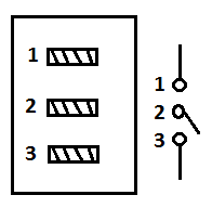
A spdt toggle switch has 3 terminals. In this video i give you the characteristics of a dpdt switch and how to wire. Terminal 1 is connected to one load or accessory terminal 3 is connected to another load or accessory. In corridor wiring circuit a lighting point is controlled from two different locations using 2 way switches. And terminal 3 can connect to any load to power any device. Terminal 1 can connect up to any load to power a certain device.
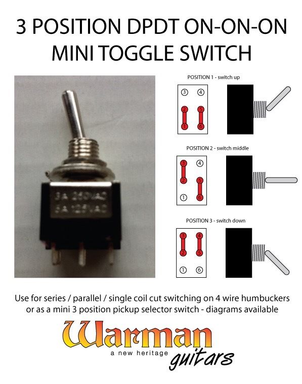
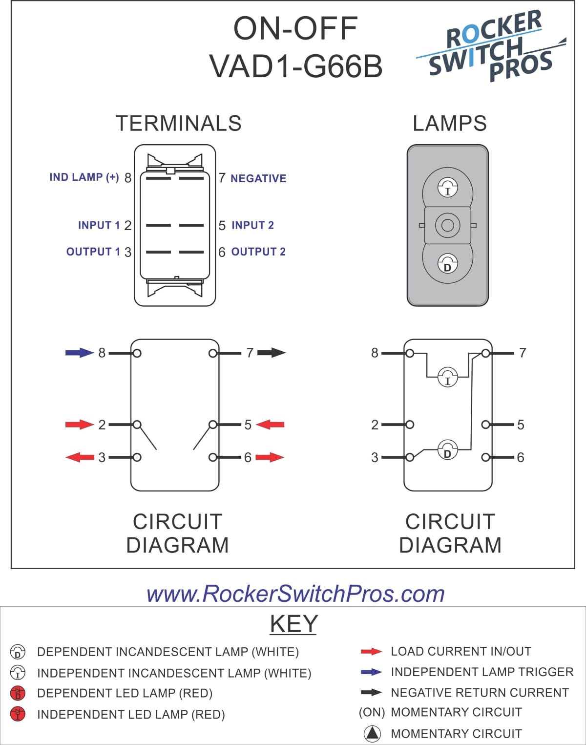
To convert connect jumper wire from terminal 3 to terminal 6 and connect terminal 4 to ground diagram f diagram g1 diagram g2 b l 2 4 3 b l 2 4 36 b l 2 4 36 jumper single pole sp double pole dp switch wiring diagrams diagrams represent both momentary contact or maintained contact switches. The switch is always making one of the two connections and flips between them. Getting from factor a to direct b. What do spst spdt dpst and dpdt mean. Basically this circuit is same like staircase wiring circuit using two way spdt switches used to control the lighting circuit in a hallway and corridors. August 19 2018 by larry a.
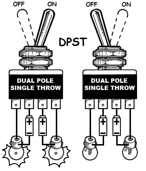
Terminal 1 is connected to one load or accessory terminal 3 is connected to another load or accessory. This is how you wire a double pole double throw dpdt switch. The objective is the same. Terminal 2 is connected to power. Switches with two pilot lights. Spdt toggle switch wiring diagram.
Gallery of Spdt Toggle Switch Wiring Diagram