Star delta starters consist of a power circuit and control circuit. A star delta starter is a type of reduced voltage starterwe use it to reduce the starting current of the motor without using any external device or apparatus.
Star Delta Starter Control Diagram Electrical For Android
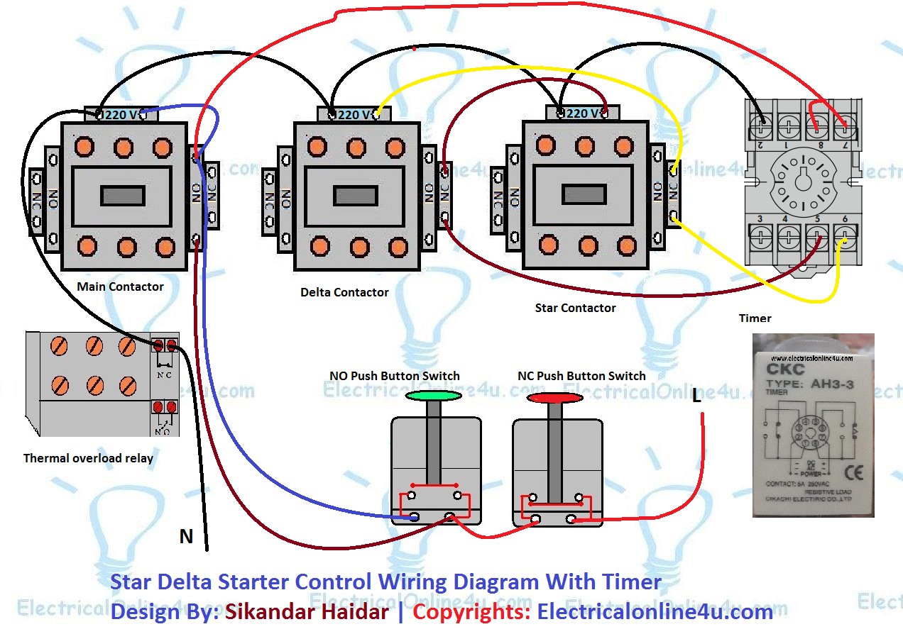
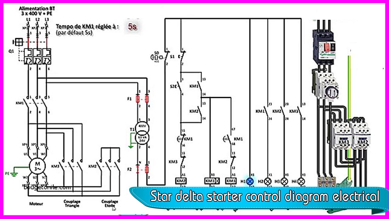
Star delta starter wiring diagram. Star delta connection circuit diagram. Star delta wiring diagram from siemens. The control circuit uses to control the starter circuit such as on off and tripping operations. This is a big advantage of a star delta starter as it typically has around 13 of the inrush current compared to a dol starter. The on delay timer diagram is also shown in the diagram. In the above star delta starter control circuit wiring diagram with timer and normally close push buttonnormally open push button switch.
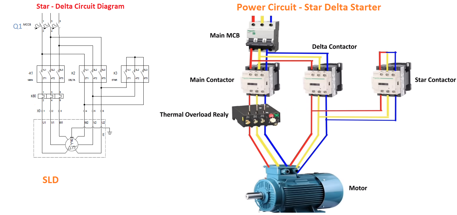
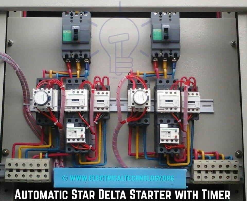
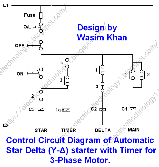
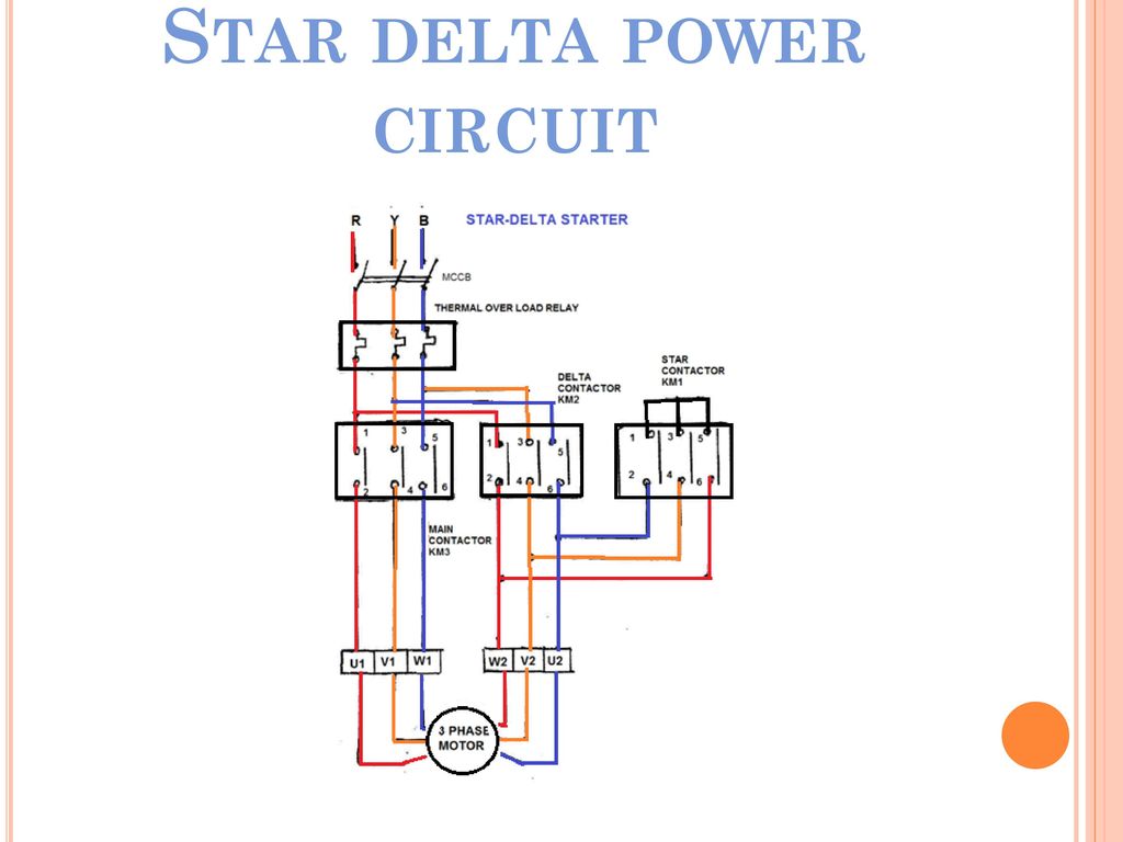
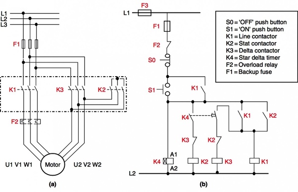
In this tutorial we will show the star delta y δ 3 phase induction ac motor starting method by automatic star delta starter with timer with schematic power control and wiring diagram as well as how star delta starter works and their applications with advantages and disadvantages. A 8 pin timer are used. By the end of this tutorial you will understand how these work. Then a thermal overload relay is connected for the protection purpose. You can see in the below figure i have shown the star delta starter connection with a three phase motor. The power circuit uses to create contact between the motor and three phase power supply.
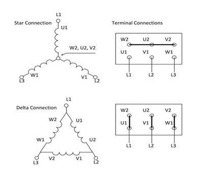
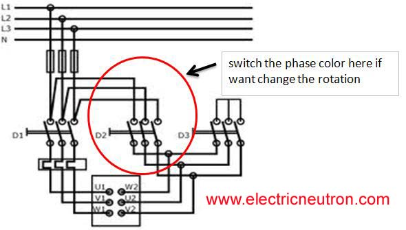
In control wiring diagram all magnetic contactors coils are rated 220 vac. First a main switch or mcb or mccb is connected to give the power supply to the circuit. Always check with your manufacturer how and if a motor can be connected to a star delta starter. Below are two examples of wiring diagrams for star delta starters from industry suppliers. Star delta starter power circuit diagram.
Gallery of Star Delta Starter Wiring Diagram