Each component ought to be placed and linked to different parts in particular manner. In the above one phase motor wiring i first connect a 2 pole circuit breaker and after that i connect the supply to motor starter and then i do cont actor coil wiring with normally close push button switch and normally open push button switch and in last i do connection between capacitor.

Run Stop Relay Circuit
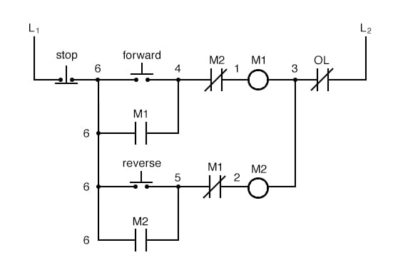
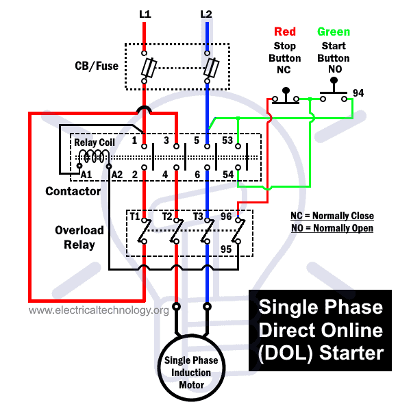
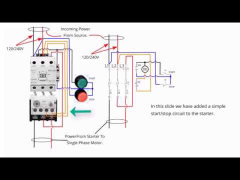
Stop start wiring diagram single phase. S1 push button switch ptb non latching stop switch. A wiring diagram is a simplified traditional photographic representation of an electric circuit. The above diagram is a complete method of single phase motor wiring with circuit breaker and contactor. It reveals the parts of the circuit as simplified shapes and the power and signal links between the gadgets. The start and stop circuits could alternatively be controlled using a plc. As always feel free to contact us with any questions.
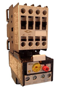
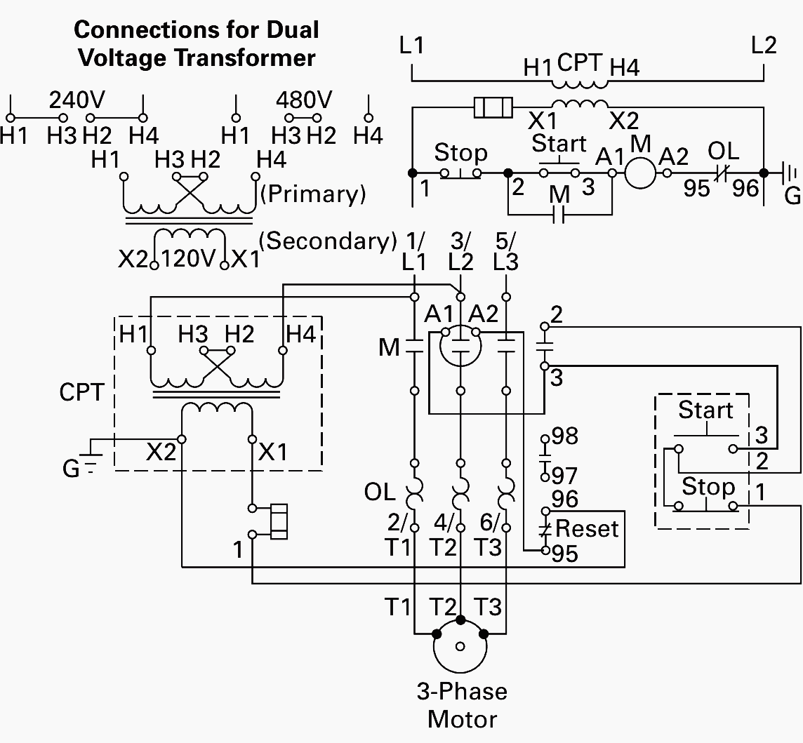
Collection of single phase motor starter wiring diagram. Wiring diagram single motor with start stop switch. Tor thermal overload relay 28a. The below wiring diagram shows how we would assemble a complete motor starter with a startstop button for a single phase motor utilizing a 3 pole contactor. 1 magnetic contactor 220vac. Electric parts needed for the wiring above.
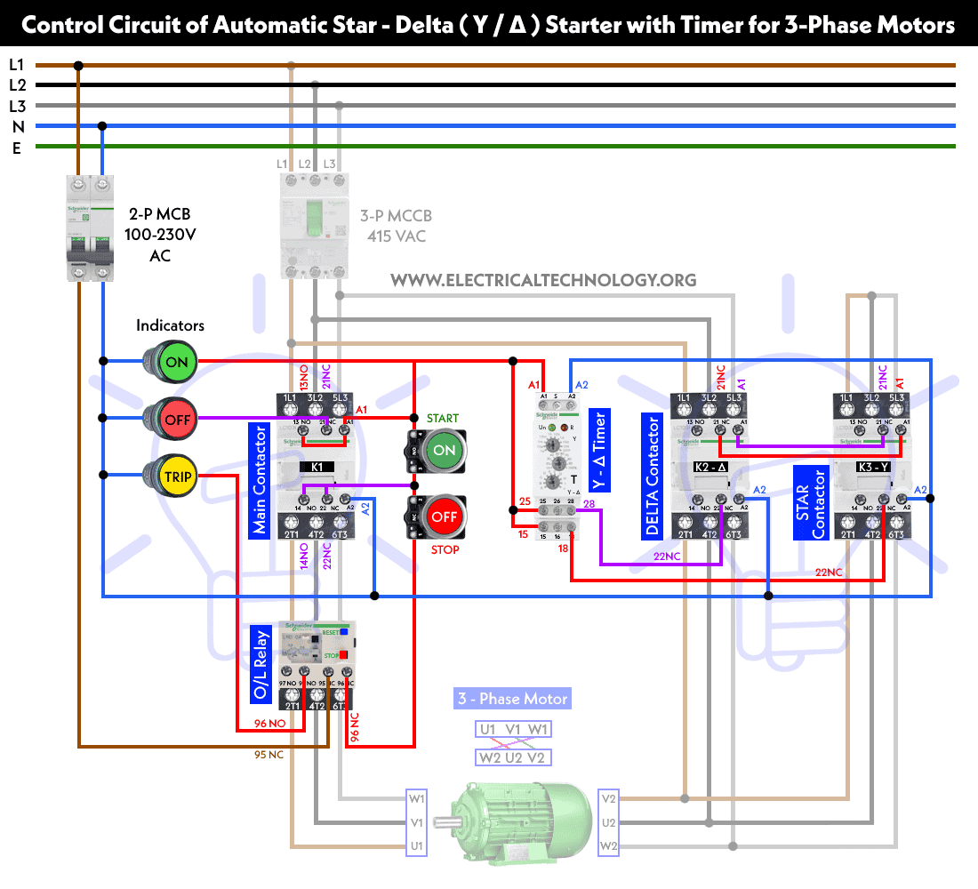
Single phase motor wiring diagram with capacitor baldor single phase motor wiring diagram with capacitor single phase fan motor wiring diagram with capacitor single phase motor connection diagram with capacitor every electrical arrangement is made up of various unique pieces. B1 mcb 5a 3 phase. Wye delta open transition 3 phase motors. It uses a contactor an overload relay one auxiliary contact block a normally open start pushbutton a normally closed stop pushbutton and a power supply with a fuse. M1 motor 15kw 380v 3phase. This diagram is for single phase motor control.
We hope this helps further your understanding of motor controls.
Gallery of Stop Start Wiring Diagram Single Phase