Here you can see there is a cut in the line wire connected to lamp 3 so the bulb is switch off and the rest circuit is working. Multiple light wiring diagram.

Window Ac Wiring Connection Diagram Ryb Electrical Ac
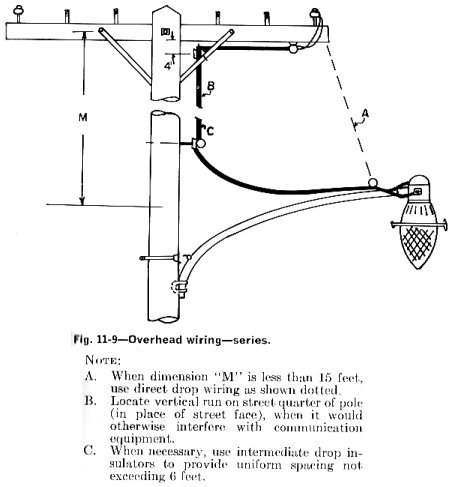
Street lighting circuit wiring diagram. Another major defect of series lighting circuit is that as all lamps or bulbs are connected between line l and neutral n accordingly if one of the light bulb gets faulty the rest of the circuit will not work as the circuit will be open as shown in fig below. Street lighting detail drawings. Thus if connections are made properly incandescent lamps should blink on momentarily when the control is. Also review the supplied maufacturers wiring diagram to verify proper wiring procedures. Streetlight wiring diagrams. It shows the elements of the circuit as streamlined forms as well as the power and also signal connections in between the tools.
Standard number title date approved 600 series 601 pull box installation 2006 602 street light standard wiring diagram 2006 603a electrical service detail underground service 2006 603b reserved 2014 604 lateral light distribution 2006 poles 610 street lights major streets 2014. Adding new street lights involves wiring the new lights to an existing power source and also wiring the control unit which will turn the lights on and off depending on the amount of light hitting the photoelectric cell. In this type the contacts are closed until the control is plugged in and energized. In fact you can this circuit for implementing any type of automatic night light. So before we get stuck in to some wiring diagrams. We have and extensive collection of common lighting arrangements with detailed lighting circuit diagrams light wiring diagrams and a breakdown of all the components used in lighting circuits.
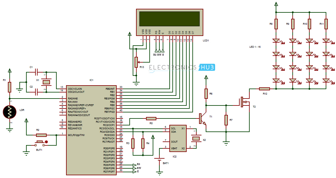
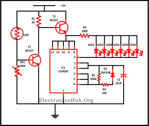
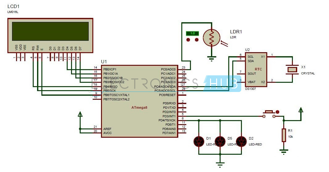
When light falls on the ldr its resistance decreases and the voltage at the base of q1 will increase which will switch on the q1 and the q2 will remain switch off. This diagram illustrates wiring for one switch to control 2 or more lights. The circuit is actually a dark detecting circuit or we can also say it dark light sensor circuitthe two transistor used in the circuit are working as switches. The circuit uses a light dependent resistor ldr to sense the light when there is light the resistance of ldr will be low. The circuit diagram present here is that of a street light that automatically switches on when the night falls and turns off when the sun rises. All photoelectric pe controls purchased by city light are of the normally closed type.
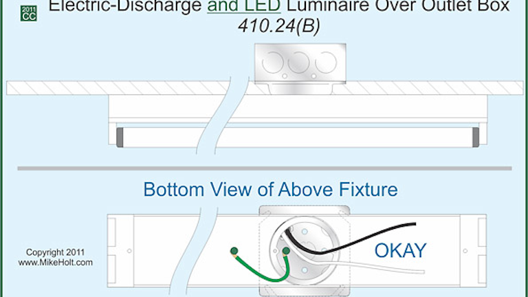
This document is a continuation of understanding early street light circuits the challenge that engineers faced with early street lighting systems involved getting the appropriate current to travel long distances without suffering excessive line loss or having to use impractically large diameter conductors. Different manufacturers wire. The hot and neutral terminals on each fixture are spliced with a pigtail to the circuit wires which then continue on to the next light. Variety of led street light wiring diagram. All the light wiring diagrams are available in the old and the new cable colours to avoid confusion. So the voltage drop across pot r2 will be highthis keeps the transistor q1 on.
December 15 2018 by larry a. The source is at sw1 and 2 wire cable runs from there to the fixtures. A wiring diagram is a streamlined conventional photographic depiction of an electrical circuit. Led street light wiring diagram.
Gallery of Street Lighting Circuit Wiring Diagram