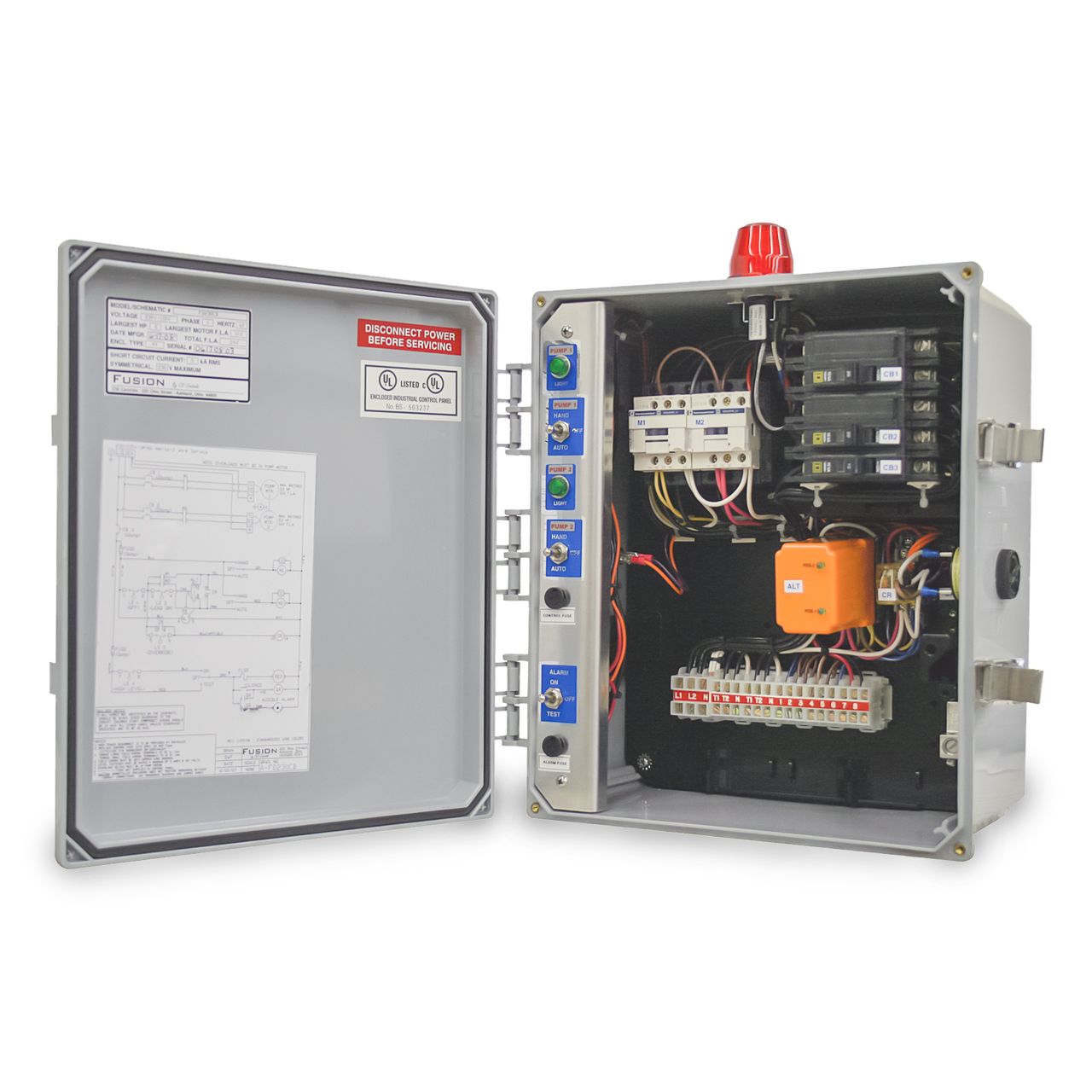
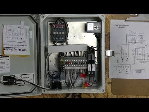
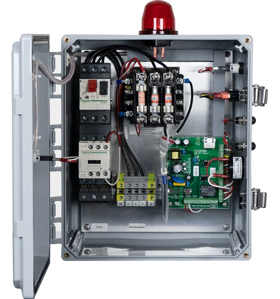
Not only a contactor but also i install the thermal overload relay which will protect the motor form burning in case of over current flow to the circuit. Edw wd s economy duplex sump pump control.
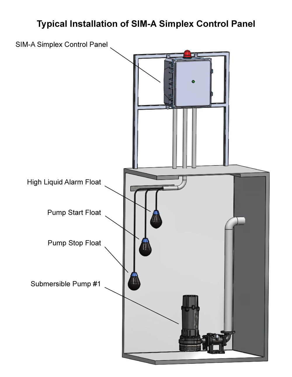
Sim A Three Phase Simplex Pump Control Panel See Water Inc
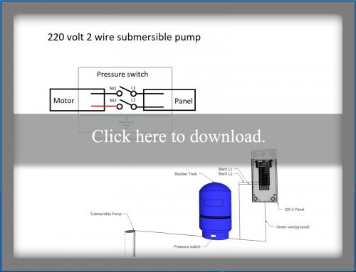
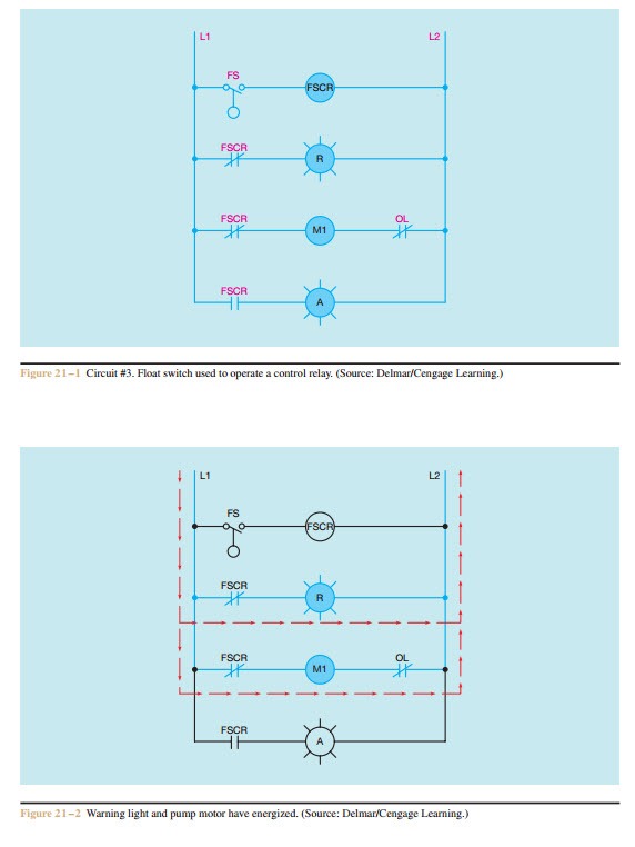
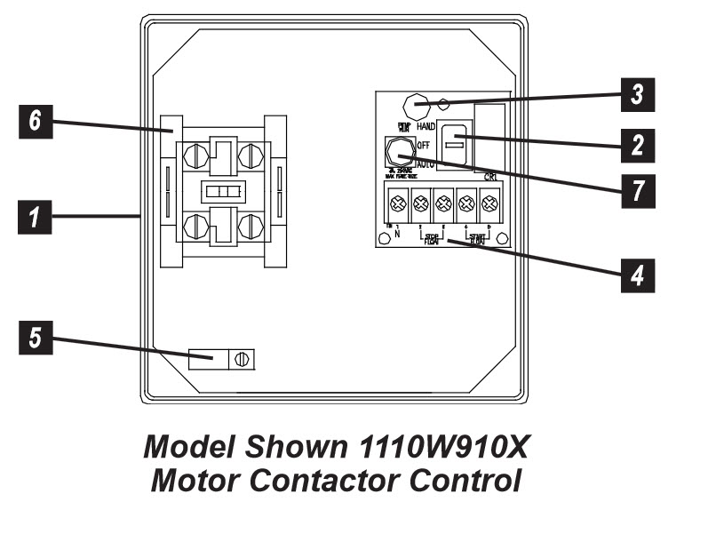
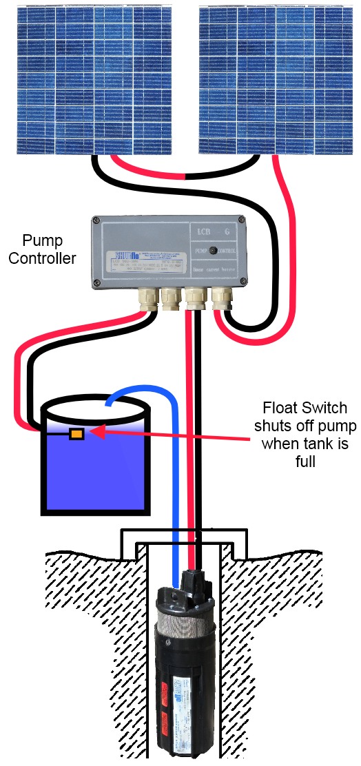
Sump pump control panel wiring diagram. 3 phase submersible pump wiring diagram. A means of disconnect for the sump pump must be located within sight and readily accessible. A wiring diagram is a simplified standard photographic representation of an electric circuit. It shows the parts of the circuit as simplified shapes as well as the power as well as signal links between the devices. The wiring connection of submersible pump control box is very simple. Electrical wiring for a sump pump circuit.
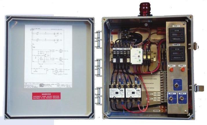
The duplex control provides alternating operation of two volt pumps. A wiring diagram is a simplified traditional photographic depiction of an electric circuit. Wellborn collection of sump pump control panel wiring diagram. Here is the complete guide step by step. Plug in ready wiring makes installation. November 6 2018 by larry a.
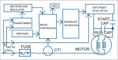
The sump pump should be protected by either a gfci outlet or a gfci circuit breaker. It reveals the components of the circuit as simplified shapes as well as the power and signal connections between the tools. Single phase submersible pump control box wiring diagram 3 wire submersible pump wiring diagram in submersible pump control box we use a capacitor a resit able thermal overload and dpst switch double pole single throw. Assortment of pump control panel wiring diagram schematic. Simplex s series pump control panels are ideal for pressure sewer or onsite orenco s1 series simplex control panel wiring diagram. The wire size that should be used for the 20 amp septic sump pump circuit should be 12 gauge.
In which i control a three phase submersible pump motor using magnetic contactor.
Gallery of Sump Pump Control Panel Wiring Diagram