Use plug infuse block kit pn 0173611 when installing tachometer with other accessories. Between the wire and the ring connector.
Suzuki Df140 Set Up Manual Pdf Fishyfish
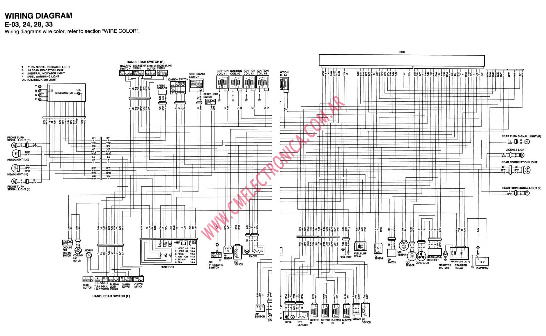
Suzuki outboard tachometer wiring diagram. Check for insulation 1. Check wires by 1. Suzuki through 2006 less than 55 hp all 60 hp 65 hp thru 1985 4. It shows the elements of the circuit as simplified forms and also the power and signal links in between the devices. A wiring diagram is a streamlined conventional pictorial depiction of an electric circuit. Signs that represent the elements in the circuit as well as lines that stand for the connections between them.
Connecting one wire at a time to the tachometer directly from the battery or the signal source on the engine. A wiring diagram typically offers details concerning the relative position and also arrangement of gadgets and terminals on the gadgets to help in building or servicing the tool. Outboard tachometer application chart all suzuki 4 strokes df40 and larger will require a tachsystem monitor or 2 system monitor gauge to properly indicate any warning or diagnostic event. With this sort of an illustrative manual you will have the ability to troubleshoot stop and complete your tasks with ease. Outboard tachometer application chart gauge is erratic a. Collection of suzuki outboard tachometer wiring diagram.
Suzuki outboard ignition switch wiring diagram youll need an extensive expert and easy to know wiring diagram. That may have been pushed into connection. Circuitry representations are made up of 2 points. Use plug in connector kit pn 0174732 when installing tachometer only. Suzuki outboard tachometer wiring diagram. Inspect the connection fix connection.
Make year model of poles. Use a wiring kit to connect the tachometer to the plug in connector on the remote control or accessory electrical cable. A wiring diagram is a kind of schematic which utilizes abstract photographic symbols to reveal all the affiliations of components in a system.
Gallery of Suzuki Outboard Tachometer Wiring Diagram