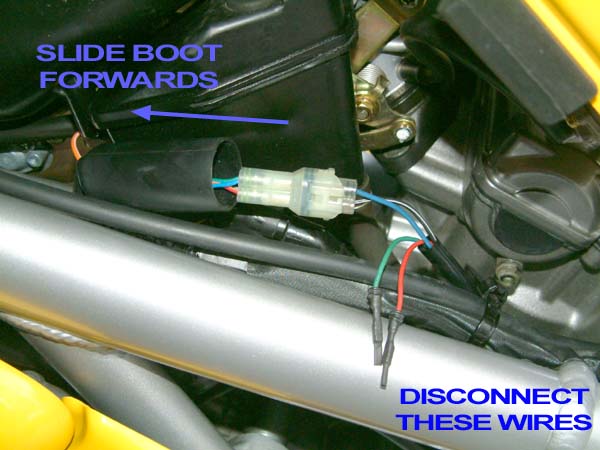
Slide the rubber boot forwards to gain access to the connector. This will eliminate the fi lightcode from showing.

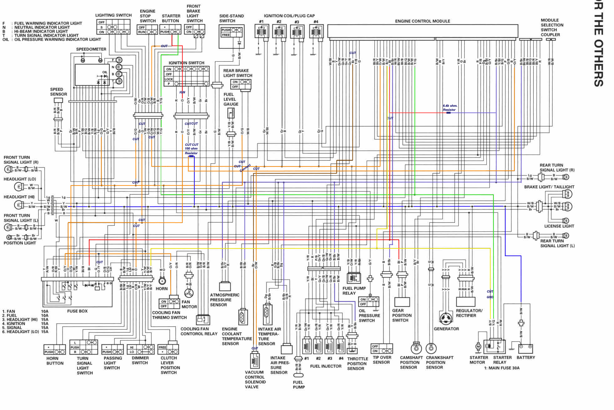
Ho 6069 Wiring Diagram For Gen 2 Sv650 Racing Wiring Diagram
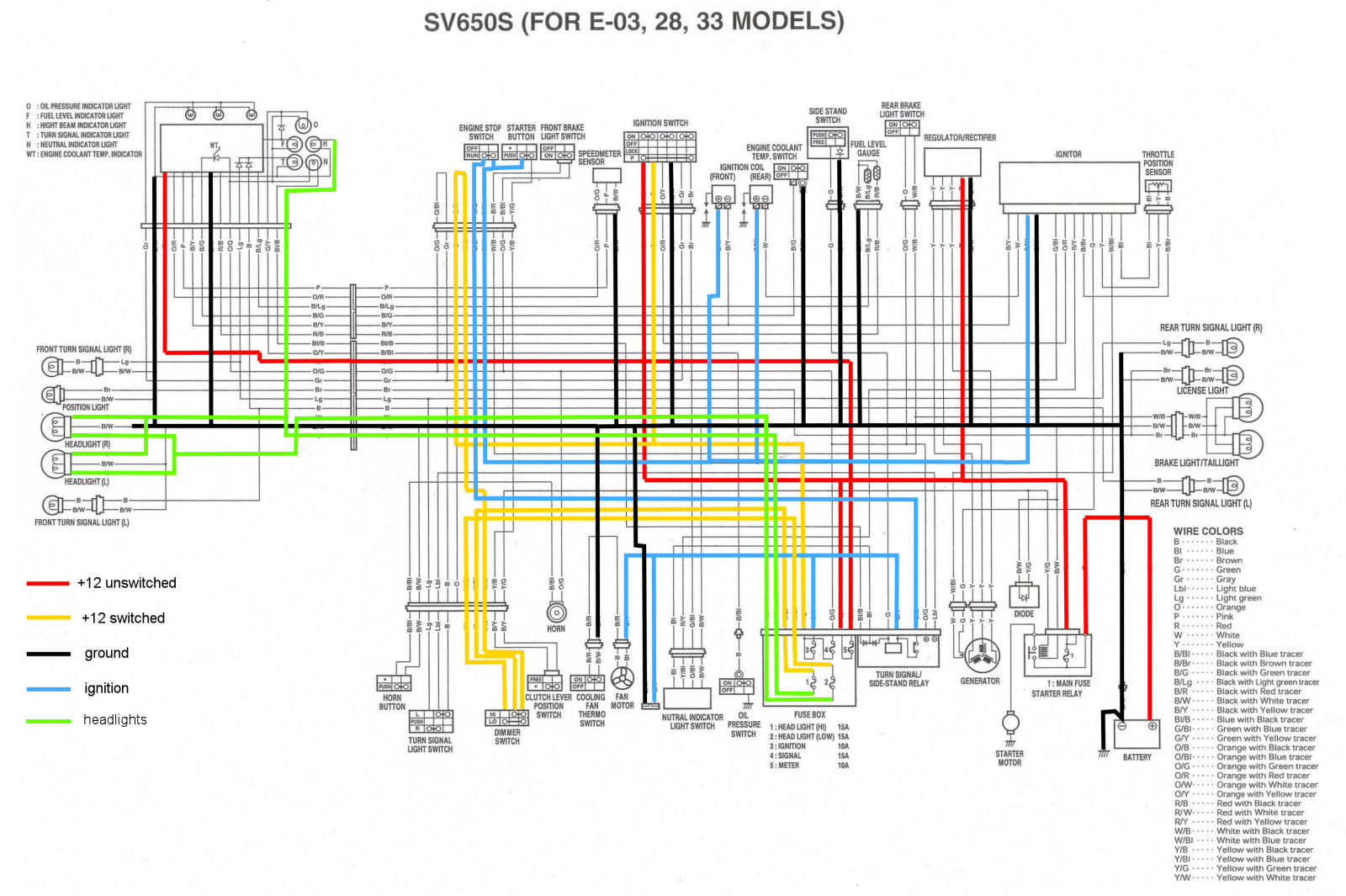
Sv650 gen 1 wiring diagram. Suzuki sv650 riders forum. Sv650s motorcycle pdf manual download. Discussion in uk motorcycles started by lozzo may 14 2007. Manufacturers reduce cost by limiting the size capacity of the vrr to the minimum required for a given bike. Mark olson may 14 2007 17. In the case of the gen 1 suzuki sv650 and lots of others i believe they were a bit over zealous in their cost reduction effort.
Solder in a 100ohm 12w resistor between the brown wire and the orangewhite wire. Zoran am well you can use schematic it is really. Sv650 tip over switch delete i like to remove the sv650 tip over sensor as to eliminate one more thing to stop your race bike from making the grid. Page 1 of 2 1 2 next lozzo guest. View and download suzuki sv650s service manual online. Come join the discussion about performance modifications racing troubleshooting maintenance and more.
Column diagram package suzuki sv svs tips amp tricks november 25th the wiring we need to disconnect is located under 1st gen wiring diagram dodge cummins diesel forum november 13th so i looked in the tech section but couldn t find it any one have the wiring harness diagram for the dash and under the hood. The 4 wires entering the connector from the rear are from the gearbox. Manuals for the 1st gen sv which i could scan for you but that wouldnt be of much use for a fi one im afraid. Gen 1 sv650s wiring diagram 01102018 01102018 5 comments on gen 1 sv650s wiring diagram i used google and in 1 minute was able to locate the following post. A forum community dedicated to suzuki sv650 owners and enthusiasts. 1st gen s model wiring diagram.
Sv650k7sk7ak7sak7 07 model wiring harness cable hose routing and sensor installation wiring harness routing for sv650s 1 throttle cable 3 to fan motor. 2 isc valve coupler 4 clamp harness without contact to bracket. Jump to latest follow 1 6 of 6 posts. 3 clutch cable 5 be careful for the lead wire not to be slackened. The good news is that these units are electrically compatible across a wide range of makes and models. A very simple process for this one.
The wiring we need to gain access to is located on the left side of the bike near the airbox where there is a rubber boot that covers a 4 pin connector see pictures 5 and 6.
Gallery of Sv650 Gen 1 Wiring Diagram