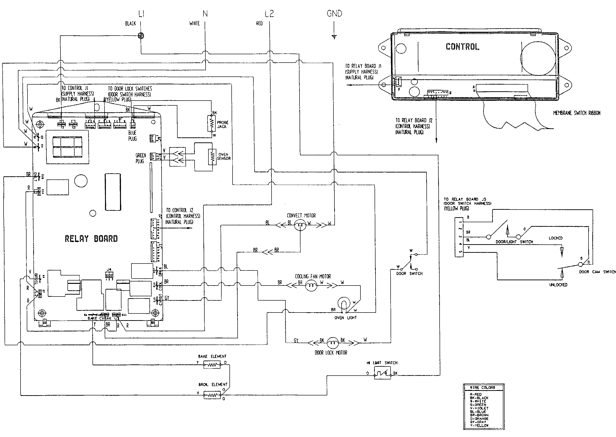
A wiring diagram is a streamlined traditional pictorial representation of an electrical circuit. How to wire a pool pump timer.
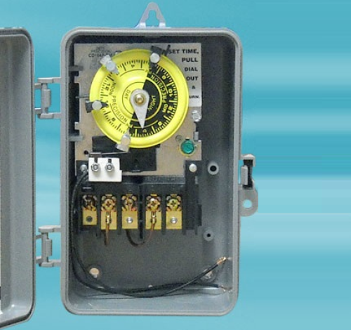
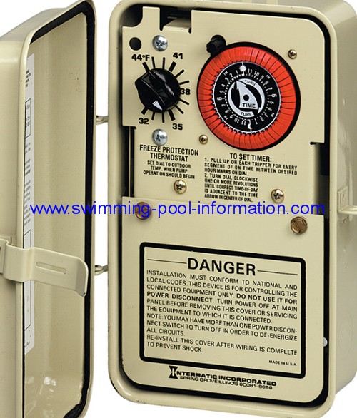
How To Wire And Connect A Intermatic Pool Pump Timer T101r
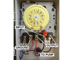
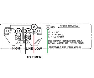
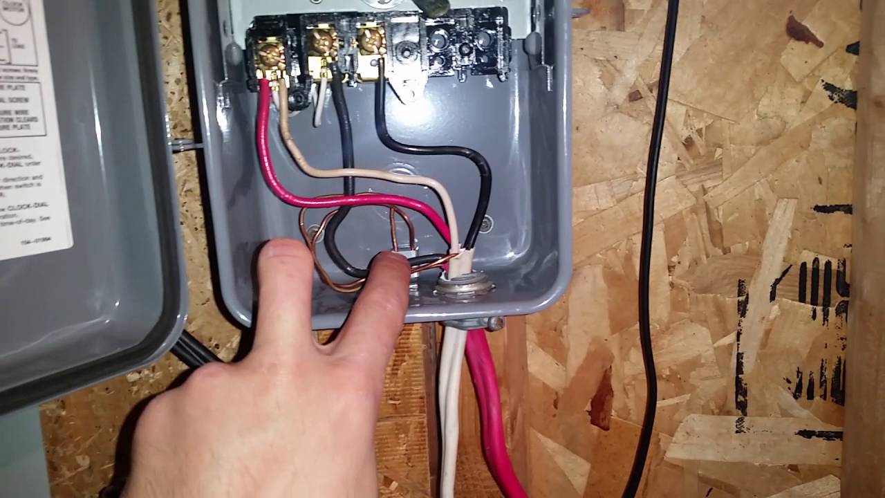
Swimming pool timer wiring diagram. It shows the components of the circuit as streamlined forms as well as the power and signal connections in between the devices. With the main service off to the house wire in gfci circuit breakers to the electrical panel. Intermatic 240v timer wiring diagram how to wire and connect a intermatic pool pump timer in wiring diagram. If your pool circuit breaker is tripping try shutting off all motors timers and lights associated with the swimming pool electrical system and try resetting the circuit breaker. Identify and locate the pool pump timers wire terminals using the timers schematic as a guide. Usually this circuit breaker has a pool tag and often connects to the.
To review a wiring diagram first you have to know just what fundamental components are consisted of in a wiring diagram and also which photographic signs are utilized to represent them. Connect an 8 gauge wire to the metal posts of the pool the pump and the metal plate on the skimmer and then wire that to the pump to bond the entire pool. Click on the image to enlarge and then save it to your computer by right clicking on the. Wellborn variety of swimming pool timer wiring diagram. Variety of intermatic 240v timer wiring diagram. March 31 2019 by larry a.
Plug in the pool pump and cover it with a weatherproof cover. The common aspects in a wiring diagram are ground power supply cable and link outcome tools buttons resistors logic entrance lights etc. Doing this isolates the equipment from the power supply wiring attached to the circuit breaker. Switch the pool pumps circuit breaker to the off position.
Gallery of Swimming Pool Timer Wiring Diagram