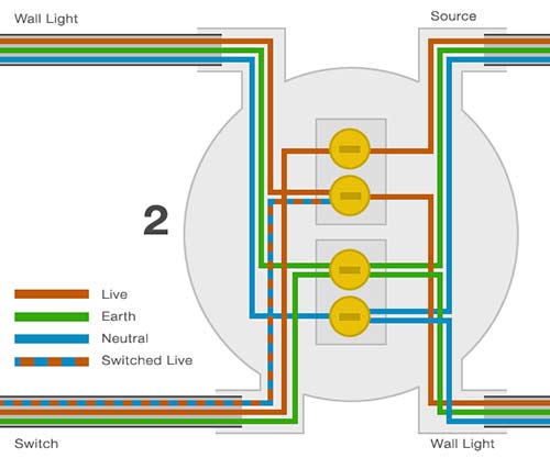
This diagram illustrates wiring for one switch to control 2 or more lights. A standard 2 wire lighting circuit is shown in figure 1.

2 Way Switch Wiring Diagram Light Wiring
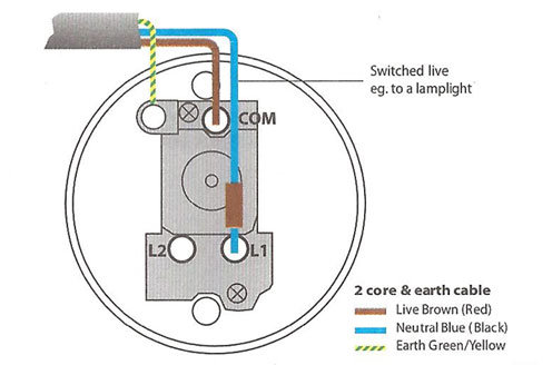
Switched live wiring diagram. The brown wire is live also know as permanent live this brings the live supply to the switch. In the wiring diagram above a hot and a neutral enter the single pole switch box. The source is at sw1 and 2 wire cable runs from there to the fixtures. For detailed step by step instructions on completing this home project. A standard 2 wire lighting system. A two conductor cable is installed from the switched outlet to feed an outlet that is live at all times.
The permanent live wire is wired into the switch and the switched live into the switched live terminal. From there a 3 conductor cable is installed to a switched electrical receptacle outlet. The neutrals are connected together using a terminal connector. The hot and neutral terminals on each fixture are spliced with a pigtail to the circuit wires which then continue on to the next light. You can also see that another live and neutral wire go to the next light switch. Outlets are split wired so that the top half of the receptacle is live all of the time and the bottom of the receptacle is controlled by the wall switch.
Switched live is only live when the switch is on this is where it gets its name from. A 2 wire system includes two wires live and switched live. The blue wire is known as the switched live and takes power to the light. Before undertaking any electrical project it is imperative that you know precisely what it is youre doing and to keep in mind that electricity can kill. Switched receptacle outlet wiring diagram depicting the electrical power feeding into an electrical receptacle box and then going to a switch and to another receptacle. With that said this electrical tutorial presents a guide to identifying the switched live wire on a lighting circuit and also explains how to rewire a ceiling rose.
Gallery of Switched Live Wiring Diagram