Copies of this manual are available at no charge from system sensor. Hardwired smoke detectors system sensor alarm wiring.
Entry Instrument Cluster Nxp
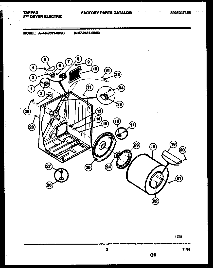
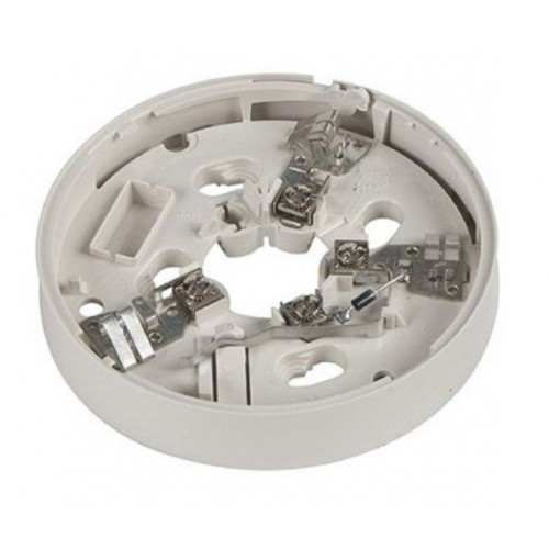
System sensor 2451 wiring diagram. Ra400z remote annunciator for 2 or 4 wire applications. System sensor 2451 and 2451th photoelectronic plug in smoke detectors installation and maintenance instructions. Wiring diagram for heating system new fire alarm wiring diagram best. Wiring diagram system sensor conventional smoke detector and. View and download system sensor 2451 2451th installation and maintenance instructions online. Before testing the detector check to ensure that the leds are blinking.
Please read the system sensor manual i56 407 guide for proper use of system smoke detectorswhich provides detailed information on detector spacing placement zon ing wiring and special applications. Atest magnet system sensor model no. 2451 2451th smoke alarm pdf manual download. To test the 2451. The system sensor 2451 photoelectronic smoke detector is ul listed to ul 268a specifically for use in no flowlow flow air handling sys. 2451th same as model 2451 above but with a 135f 57c fixed temperature heat sensor.
System sensor smoke detector wiring diagram collection system sensor d4120 wiring diagram. If they are not the detector has lost power check the wiring or it is defective return for repair. Mod400r field test module for all of the system sensor 400 series smoke detectors. Test coil 4 position terminal block 24v 120 vac 220240 vac 9 10 a c available power inputs. Place the magnet against the cover opposite the test. For instal lations in canada refer to can4 s524 standard for the.
Use with any 400 series plug in detector. Rtc ring replacement of b404bt.
Gallery of System Sensor 2451 Wiring Diagram