All spectralert advance products are suitable for use in synchronized systems. An initial appearance at a circuit representation could be confusing however if you could read a metro map you could read schematics.

Wiring Diagram Smoke Detector System Sensor Electrical Wires
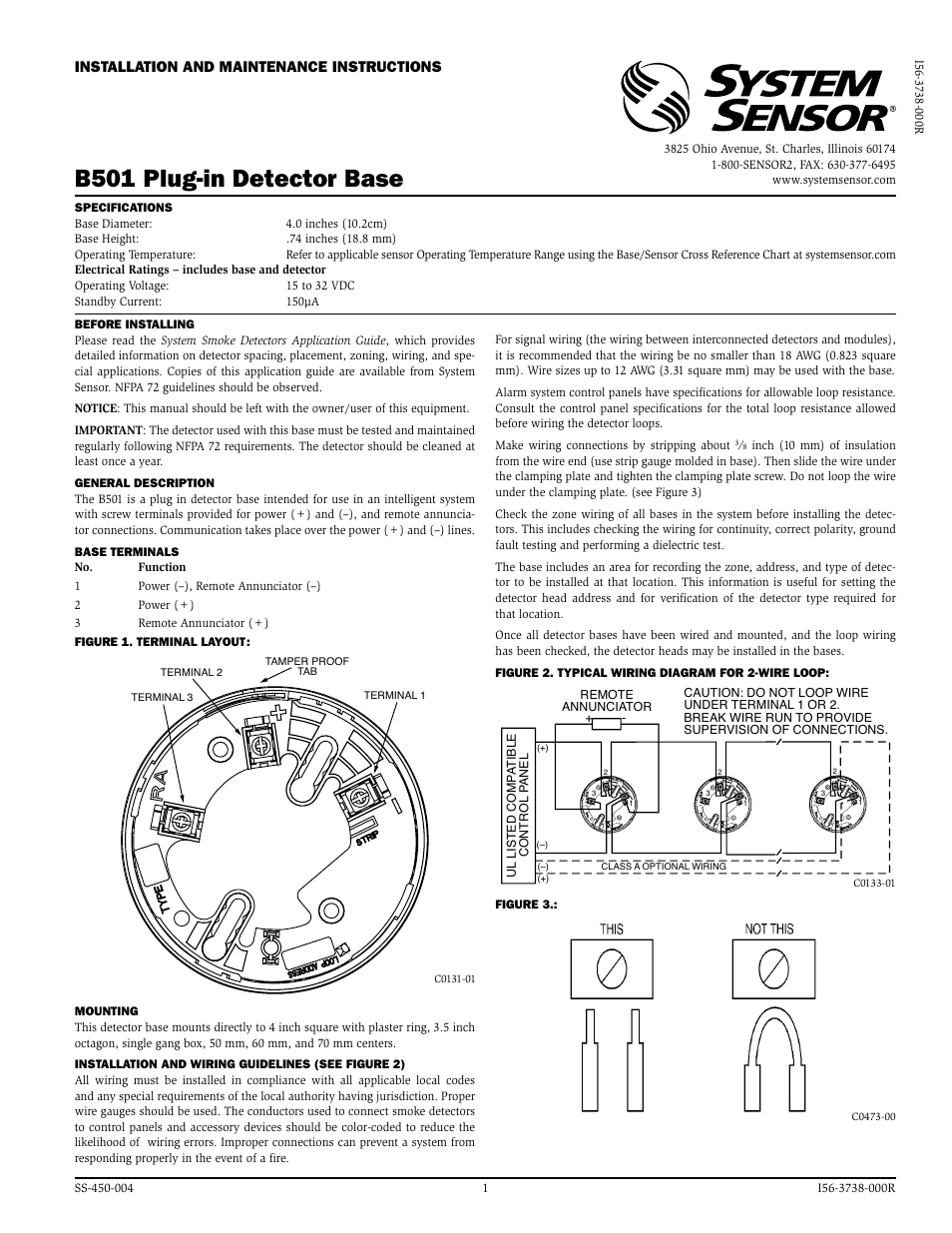
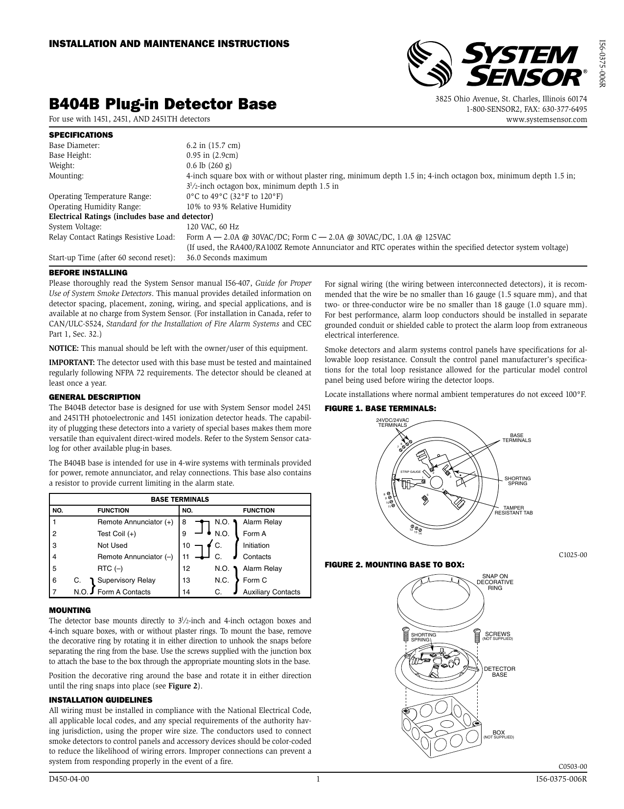
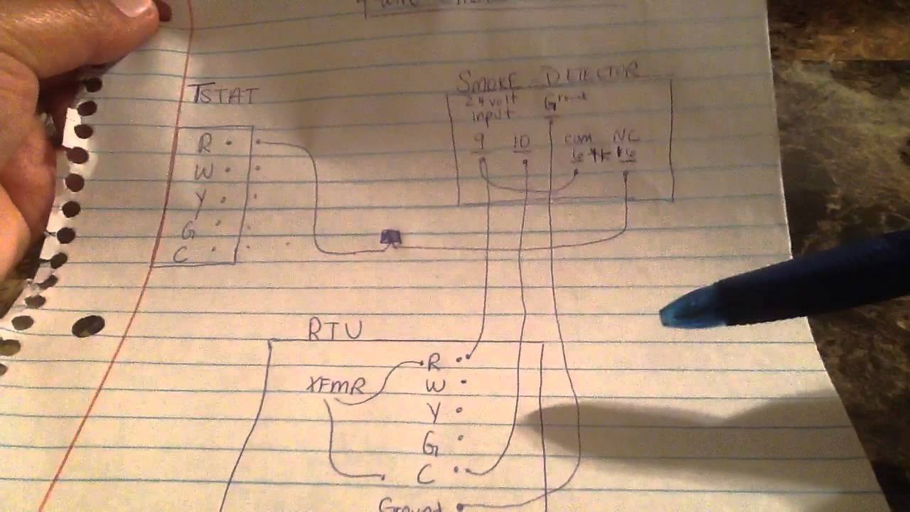
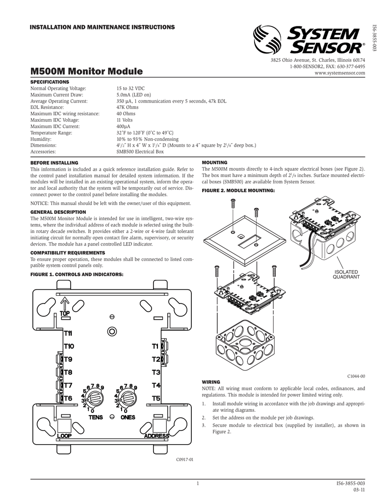
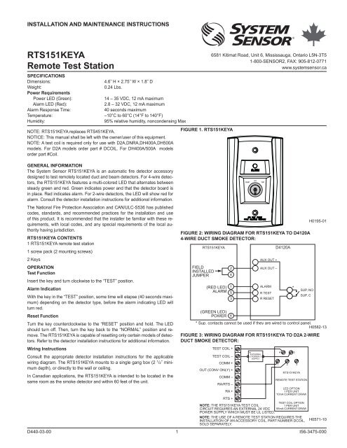
System sensor wiring diagram. Nfpa standards 72 and 90a should also be refer enced for detailed information. Wiring diagram for rts451 to dh100acdc 4 wire duct smoke detector figure 3. Read system sensors applications guide for duct smoke detectors hvag53 which provides information on detector spacing placement zoning wiring and special applications. The non polarized screw terminals on the back of the detector will accept 1422 awg wire. Refer to detector installation instructions for additional information. Please also refer to canulc s524 standard for.
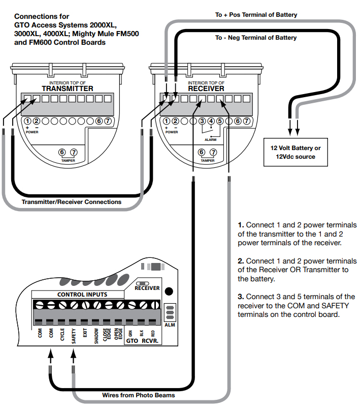
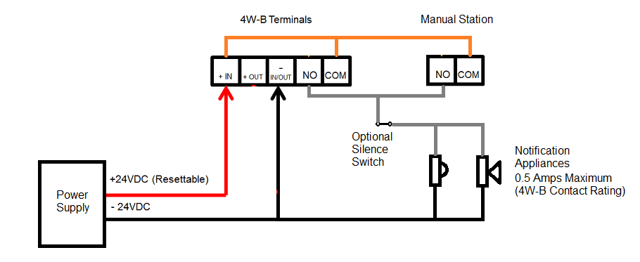
It is to be used with ul listed separately supplied power 4 wire control panels only. For best system performance all wiring should be installed in separate grounded conduit. The 4 wire products are in tended for systems which have separate wiring circuits for the horn and strobe. The 2 wire products fit systems where a single nac controls both horn and strobe. System sensor smoke detector wiring diagram. Cop ies of this manual are available at no charge from system sensor.
System sensor model beam1224beam1224s is a long range projected beam smoke detector designed to provide open area protection. Wiring diagram for rts451 to dh100 2 wire duct smoke detector 15 20 2 11 2 alarm signal 1 aux. Assortment of system sensor smoke detector wiring diagram. Power reset test red led alarm. It shows the elements of the circuit as simplified forms and the power as well as signal links in between the gadgets. Can prevent a system from responding properly in the event of a fire.
The detector consists of a transmitterreceiver unit and a reflector. Read the system sensor guide for proper use of smoke detectors in duct applications a05 1004 which provides information on detector spac ing placement zoning wiring and special applications. Resetting only certain system sensor models of detectors. A wiring diagram is a simplified traditional pictorial depiction of an electric circuit. Nfpa standards 72 and 90a should also be referenced for detailed information. Psp1 products system sensor system sensor.
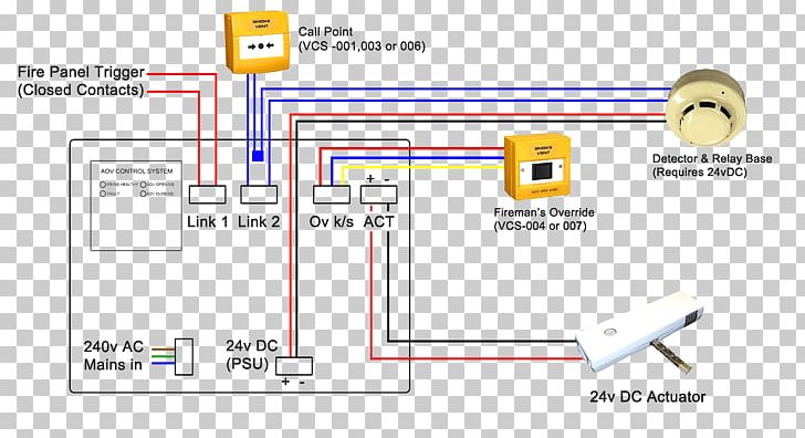
Please thoroughly read the system sensor manual i56 407 guide for proper use of system smoke detectors which provides detailed information on detector spacing placement zoning wiring and special applications. System sensor smoke detector wiring diagram a novice s guide to circuit diagrams. The system sensor mdl3 module may be used to provide synchronization. Do not mix fire alarm system wiring in the same conduit as any other electrical wiring. System sensor is a global manufacturer of fire and life safety devices in smoke detection carbon monoxide detection and notification technology.
Gallery of System Sensor Wiring Diagram