For chrysler blue gold and silver boxes ford standard electronic ignitions and most other oem standard cd and electronic ignitions. Wiring your new autometer tachometer into your car will complete the installation.

Alternator Wiring Diagram Tachometer Lihghtings 1 Rmnddesign Nl
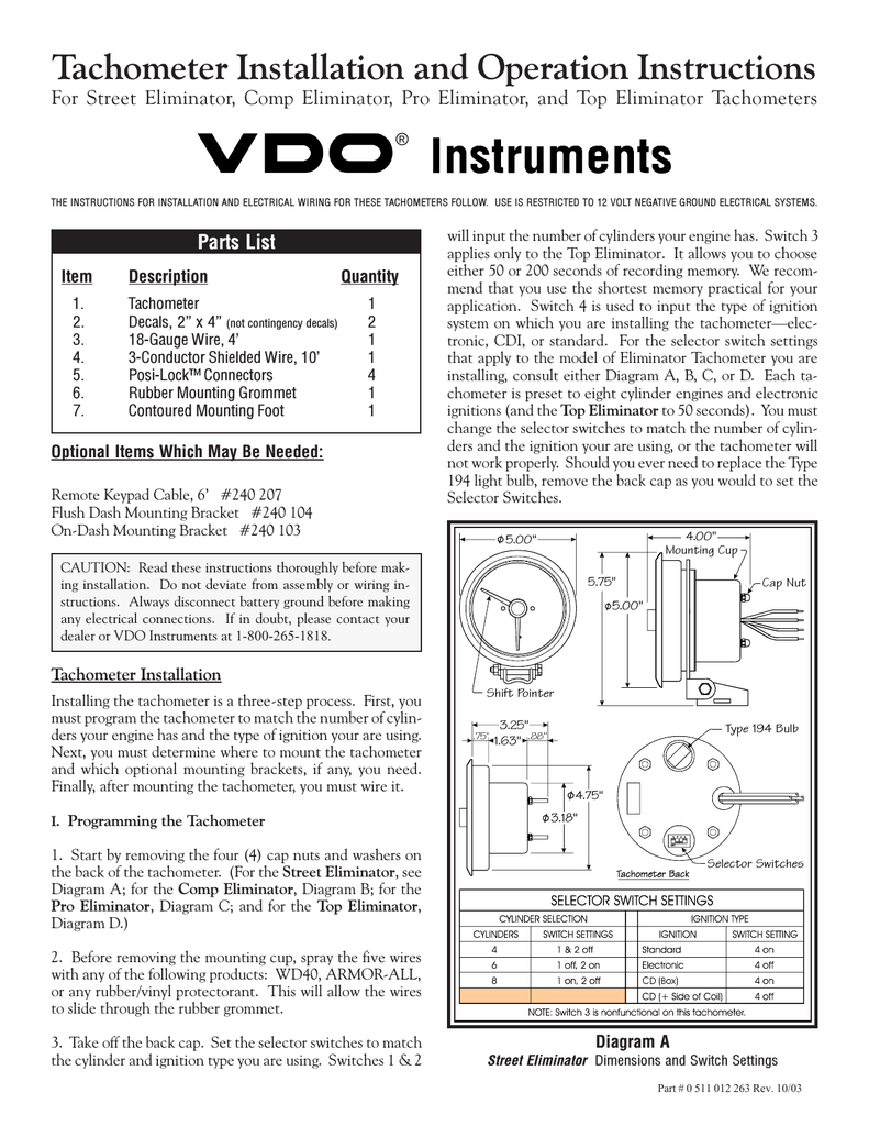
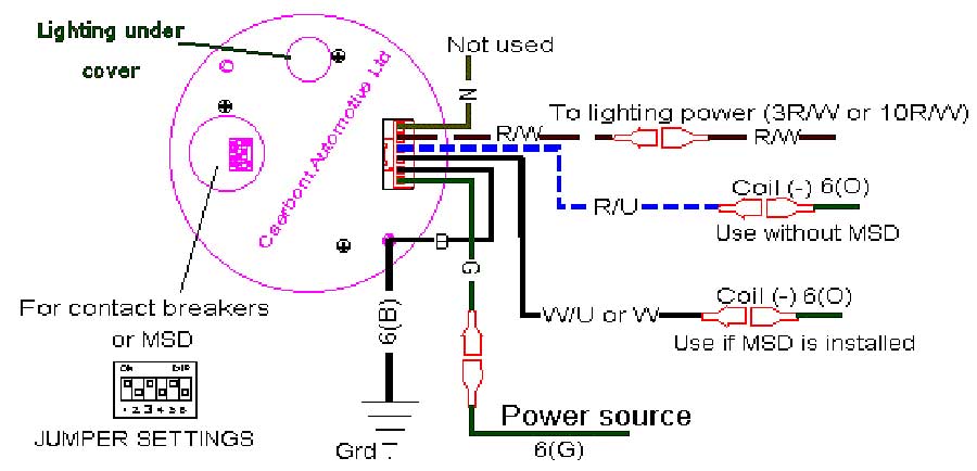
Tachometer wiring diagram. August 14 2018 by larry a. The tachometer is designed to show the engine rpms or rotations per minute. Attach the tachometer backlighting wire. Black yellow stripe. Existing holes will have a rubber grommet to protect the wiring. To change the ppr on tachs with three buttons follow the steps below.
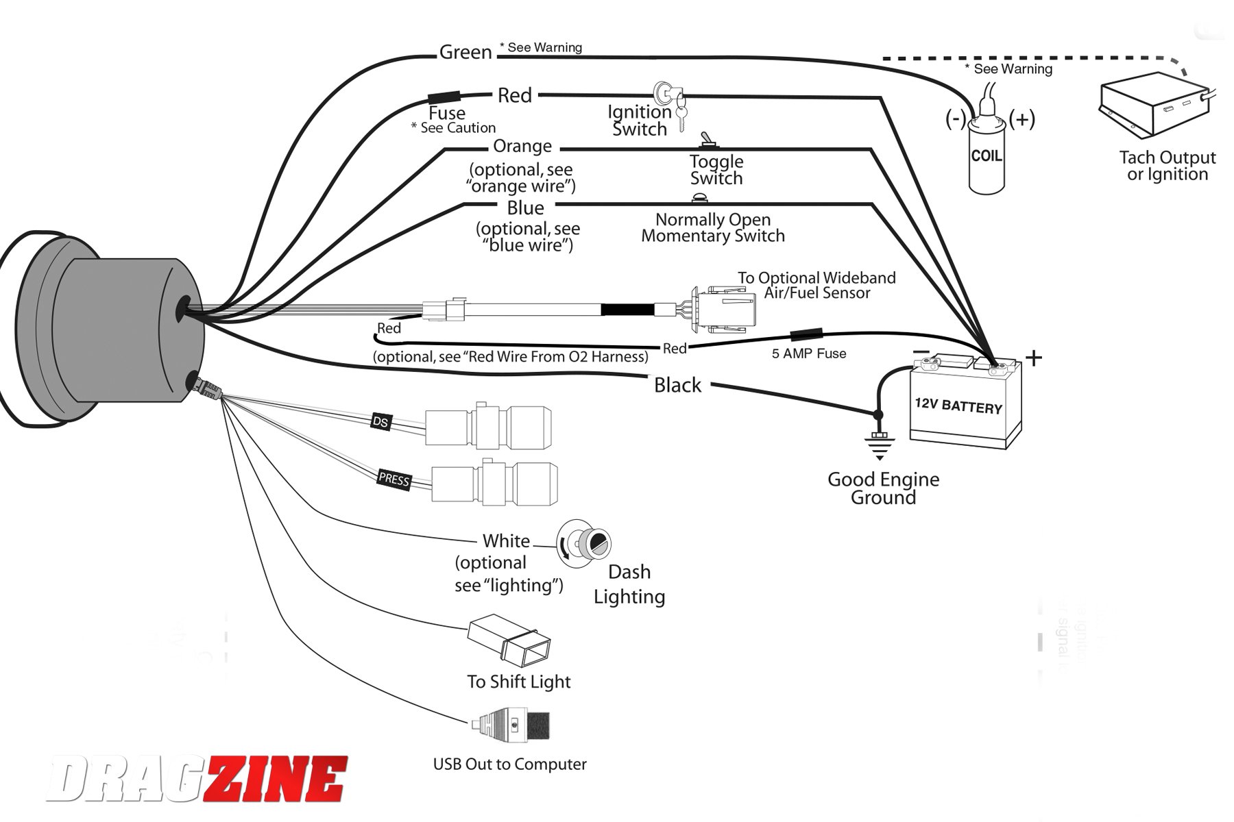
The wires were cut leaving extra length stripped and then joined permanently with butt connectors. Provide power to the tachometer backlighting. Variety of autometer tach wiring diagram. Do not start the engine. The pointer will move to a. 12v battery coil ignition coil tach base can be mounted in either direction for convenient mounting.
Autometer has designed their tach to be used with four six. It reveals the components of the circuit as simplified shapes and also the power and also signal connections in between the devices. It reveals the elements of the circuit as simplified forms as well as the power and signal connections in between the tools. Ignition switch to 12 volt positive. Wire to a junction and attach the wire from pin 4 at this junction ie. The wiring diagram shown is a typical installation.
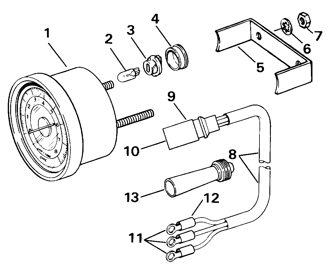
With no power applied to the tach press and hold the set button. Use an existing hole in the firewall to pass the black and green wires through to the engine bay. Apply power to the tach by turning the ignition key to the accessory or on position. Refer to diagram d. White red black green grommet. Temperature switch to warning horn andor.
Connect a wire from pin 5 to a constant 12 or 24 volt source. Attach the wire from pin 3 to a ground negative source. The tachometer is configured at the factory for 4 ppr. Red purple stripe. Un fused wire from battery. A wiring diagram is a simplified standard photographic representation of an electric circuit.
Cut out a notch in this grommet to pass the wires through or drill a new hole for the wires to be sent. Fuel sender to gauge. Additional wire need to supplement the length of the auto meter tach harness came from painless. A wiring diagram is a streamlined standard pictorial representation of an electrical circuit. Protected fused wire from battery andor protected 12 volt to trim panel control. Shorting or stop circuit.
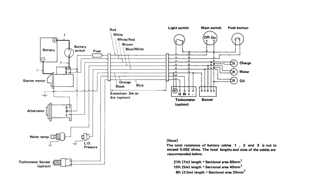
Apply power to the tachometer by attaching the power input wire of the tachometer to the 12 volt dashboard lighting supply of the car. Wiring connect the tachometer wires as shown. Once you have selected a mounting location you can run the four wires that operate the tachometer. One such source can always be found where the battery is attached to the metal frame of the vehicle. Variety of yamaha outboard tachometer wiring diagram. With the tachometer and wiring in place finishing the job is easy.
September 7 2018 by larry a. Locate the 12 volt switched dash lighting supply for the dashboard on the car fuse box.
Gallery of Tachometer Wiring Diagram