Hot deals 2896 views. Tb6600 stepper motor driver controller vcc pin red wire in the diagram.

4 5a Bipolar Stepper Motor Driver Tb6600 Electrical
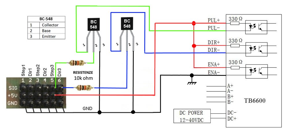
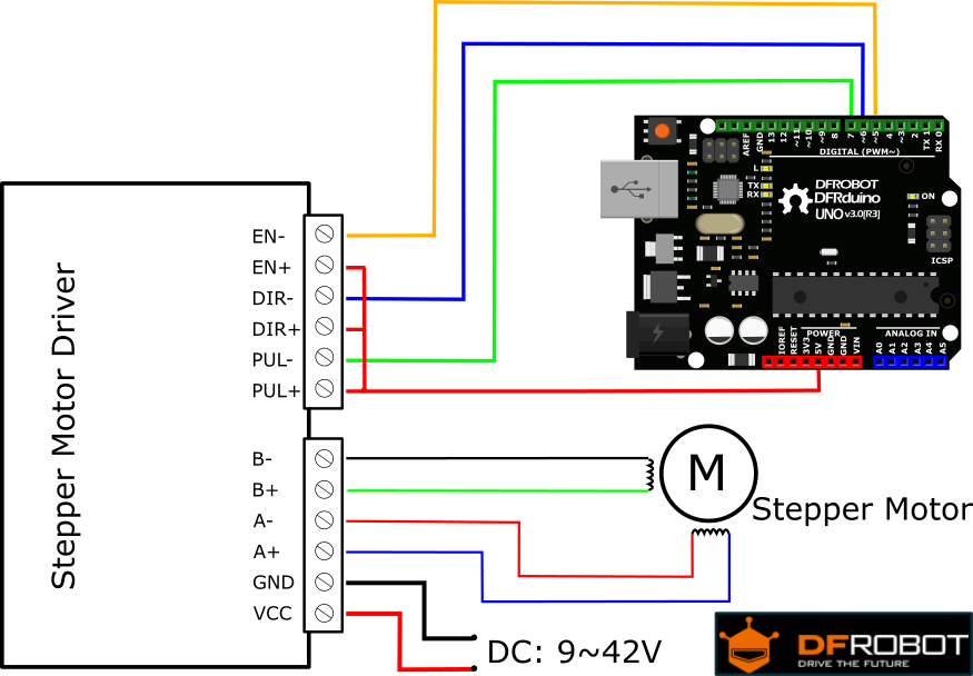
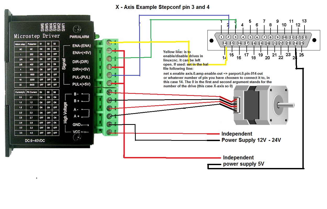
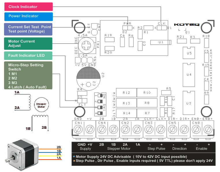
Tb6600 wiring diagram. And it is able to. ① step pulse signal pul pul. The output of the 33 vdc dc to dc converter is routed to pins 2 4 and 6 of the tb6600 stepper motor driver controller blue wire in the diagram. ② direction signal dir dir. Nema 34 125nm closed loop stepper motor kit hybird servo driver hb860h 86hb250 156b 86 2 phase s duration. It is compatible with arduino and other microcontrollers that can output a 5v digital pulse signal.
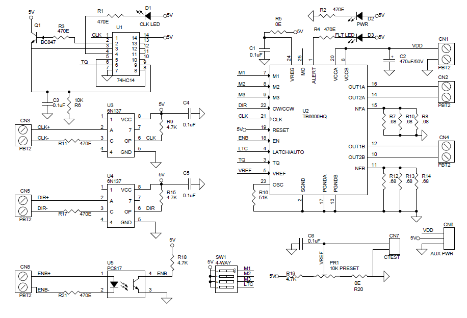
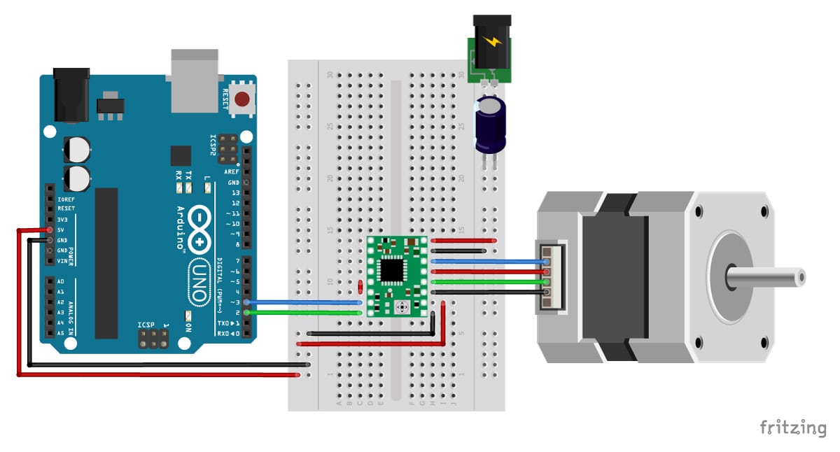
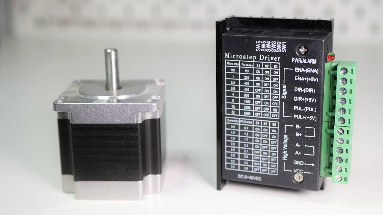
I have done research on the forum google etc and cant seem to find an easy to understandwiring diagram on replacing g shield with tb6600 drivers. You acctually can use easydr. Zyltech toshiba tb6600 driver instructions. A quick post about wiring tb6600 stepper driver which is based on tb6600hg chip. The tb6600hg is a pwm chopper type single chip bipolar sinusoidal micro step stepping motor driver. Stepper motor used in this demo is 23hs22 2804s 28a nema23.
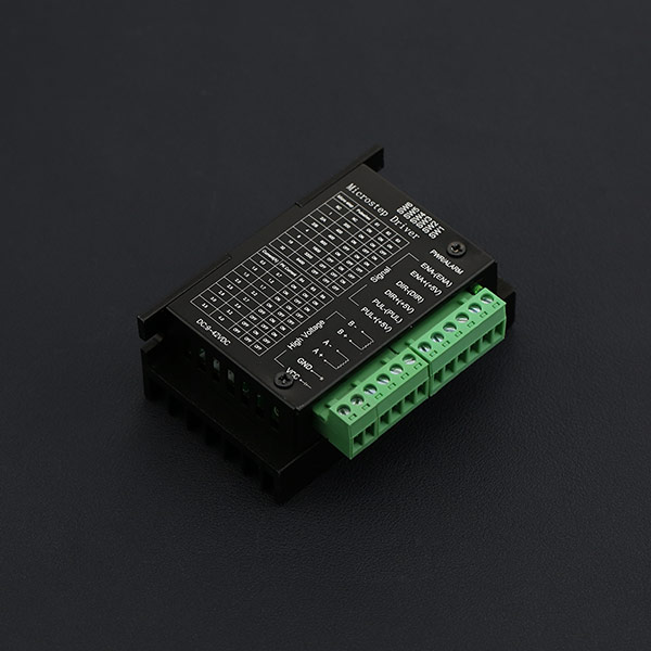
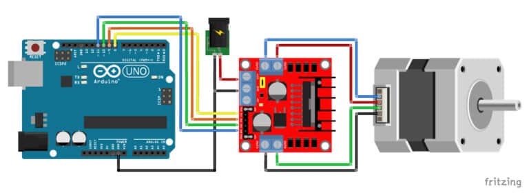
It has model marking on the back that says bl tb6600 v12. The driver supports common cathode and common anode circuit you can select one according to your demand. Tb6600 wiring diagram arduino. Today we are going to talk about the step motor again. Wiring diagram with arduino cnc shield. This means that we connect all the negative sides of the control signal connections to ground.
Zyltech toshiba tb6600 driver instructions. Tb6600 arduino stepper motor driver has a wide range power input 942vdc power supply. Wiring instructions there are three input signals in all. I have 4 of these and wanted to see if anyone has an idiot proof wiring schematic. Tb6600 arduino stepper motor driver is an easy to use professional stepper motor driver which could control a two phase stepping motor. The connections are also given in the table below.
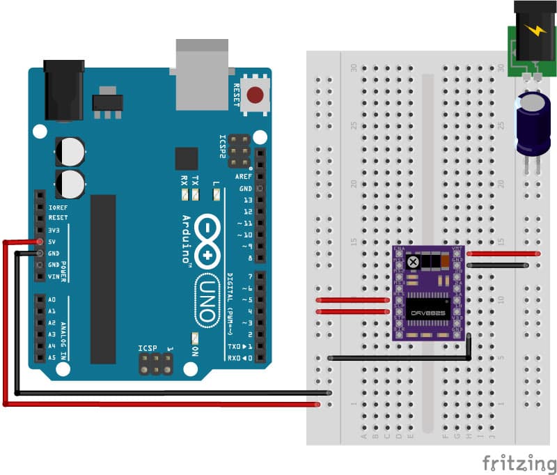
I just wired a 60a sub panel into my house but cant seem to figure this out. Forward and reverse rotation control is available with 2 phase 1 2 phase w1 2 phase 2w1 2 phase and 4w1 2 phase excitation modes. I have 4 of these and wanted to see if anyone has an idiot proof wiring schematic. But you can use a arduino nano too if you have one. Here i use one without black plastic casing. And it is able to.
Tb6600 stepper motor driver with arduino uno and stepper motor wiring diagram in this tutorial we will be connecting the driver in a common cathode configuration. It is also routed to the input of the 33 vdc dc to dc converter again a red wire in the diagram. ③ off line signal en en.
Gallery of Tb6600 Wiring Diagram