Parts list collapse expand clear. View and download simrad tp10 user manual online.

A18b7 Ansul Wiring Diagrams Wiring Resources
Tp100 wiring diagram. These modules have no internal electronic rev limiter such as the vw tp100 modules and are compatible with any engine management system aftermarket or standardfor eg. A wiring diagram is a streamlined standard photographic depiction of an electrical circuit. Temperature sensing maxim. Assortment of rtd pt100 3 wire wiring diagram. Aftermarket tp100 ignition module of high quality built by dicktator with high qulaity electronic igfet components. Refer to the diagram below and check that the belt tension is within 3mm.
The bearing with the two screws. Fit the tiller connector e02607 into the end of the push rod e02522 and screw in finger tight. Wiring there are 2 wiring methods for the rtd module and pt100 temperature sensors two wire and three wire connections. Show 3d top left front right bottom back download cad drawings. You should follow the wiring diagram ensuring you place the single white wire for 3 wire on one side of the circuit and the two red wires on the other. We have actually gathered several pictures with any luck this photo is useful for you as well as help you in finding the response you are trying to find.
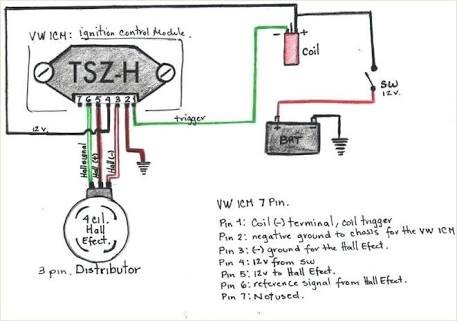
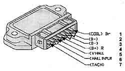
A1b1 a2b2 and c1c2. The output will normally only have two terminals as a 4 20ma device will almost certainly be loop powered. 3 wire pt100 wiring diagram welcome to my site this message will discuss concerning 3 wire pt100 wiring diagram. It shows the components of the circuit as streamlined shapes and also the power and also signal links between the gadgets. Tp100 ignition module short redyellow hall ve brown rev counter input hall v ignition 12v 0 5 green magnetic dissy toyota honda etc or fiat uno crank trigger magnetic ve thick red purple 1mm black water temp 5v supply greyred or greyblue signal ground black as seen from component side 1mm black green magnetic ve battery fuel pump. Tp10 marine equipment pdf manual download.
When wiring with two wires first jumper across a1 and b1and a2 and b2 respectively then connect pt100 sensors and to the rtd module according to the following diagram on the left. In other words the 2 wires connected to the output provide the power supply in but. Hall effect pcbfit the hall effect pcb onto the 2 pillars using 2 nylon washers.
Gallery of Tp100 Wiring Diagram