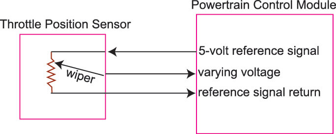
Throttle position sensor wiring diagram dodge throttle position sensor wiring diagram ford throttle position sensor wiring diagram gm throttle position sensor wiring diagram every electric structure is composed of various different components. Throttle position sensor tps wiring terminations gndrtn signal 5v terminal location in connector a b c bs3 harness wire color black whitered red gndrtn signal 5v terminal location in connector b c a bs3 harness wire color black whitered red gndrtn signal 5v terminal location in connector a b c ford wire color black green orange.
Kia Amanti Questions Can Anyone Tell Show Me The Wiring
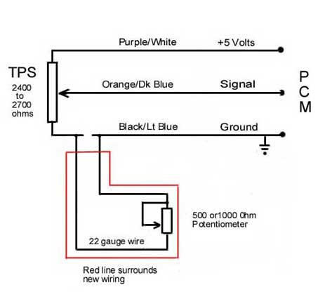
Tps wiring diagram. Otherwise the arrangement wont work as it ought to be. The throttle position sensor tps wiring diagrams and info in this page apply only to 1997 1998 16l honda civic. Red is power to tps blue is wiper connect here. Colors are at ecu. Brnwht wires feeds the tps 5 volts dc. Pinkblack wire black ground under tank near tps harness there is a length of unsleeved wire for easy wire access.
Throttle position sensor tps wiring diagram. The gryred wire feeds ground. Each part ought to be placed and linked to different parts in particular manner. Dodge throttle position sensor wiring diagram this is easy to test just jiggle youre tps wire. The grywht wire carries the tp signal to the pcm. Throttle position sensor tps wiring diagram 1997 1998 ford 46l 54l.
Before buying this kit or the tps kit we recommend you test your car by letting your car idle with the hood open and jiggling the wires going to either the tps wiring tps connects to the throttle shaft and the iac is off to the side of the. The pcm provides 5 volts dc on the yelblu wire to both the throttle position sensor fuel tank pressure sensor and the egr valve lift sensor on vtec e only. R aul otto meono 20081029. F150 f250 f350 crown victoria e150 e250 e350. Marc jon scott 20100525.
Gallery of Tps Wiring Diagram