A wiring diagram is a streamlined conventional pictorial representation of an electric circuit. Trailer breakaway box wiring diagram trailer brake battery box wiring diagram trailer brake box wiring diagram trailer breakaway box wiring diagram folks understand that trailer is a vehicle comprised of very complicated mechanics.

Curt 52025 Trailer Breakaway Battery Charger
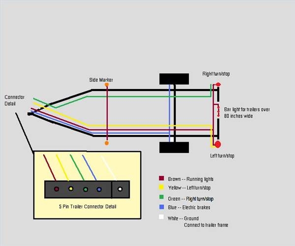
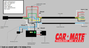
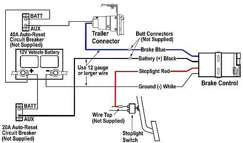
Trailer breakaway wiring diagram. Connect the breakaway switchs other lead to the blue wire with a scotchlok connector. You may have to cut into the trailer wirings sheathing to find the wire. It shows the components of the circuit as streamlined shapes and the power and also signal connections in between the devices. This automobile is designed not just to travel one place to another but also to carry heavy loads. However if the safety chains fail the breakaway kit acts as a last line of defense against a runaway trailer. Also it must connect with things if included that use the aux power and back up lights too.
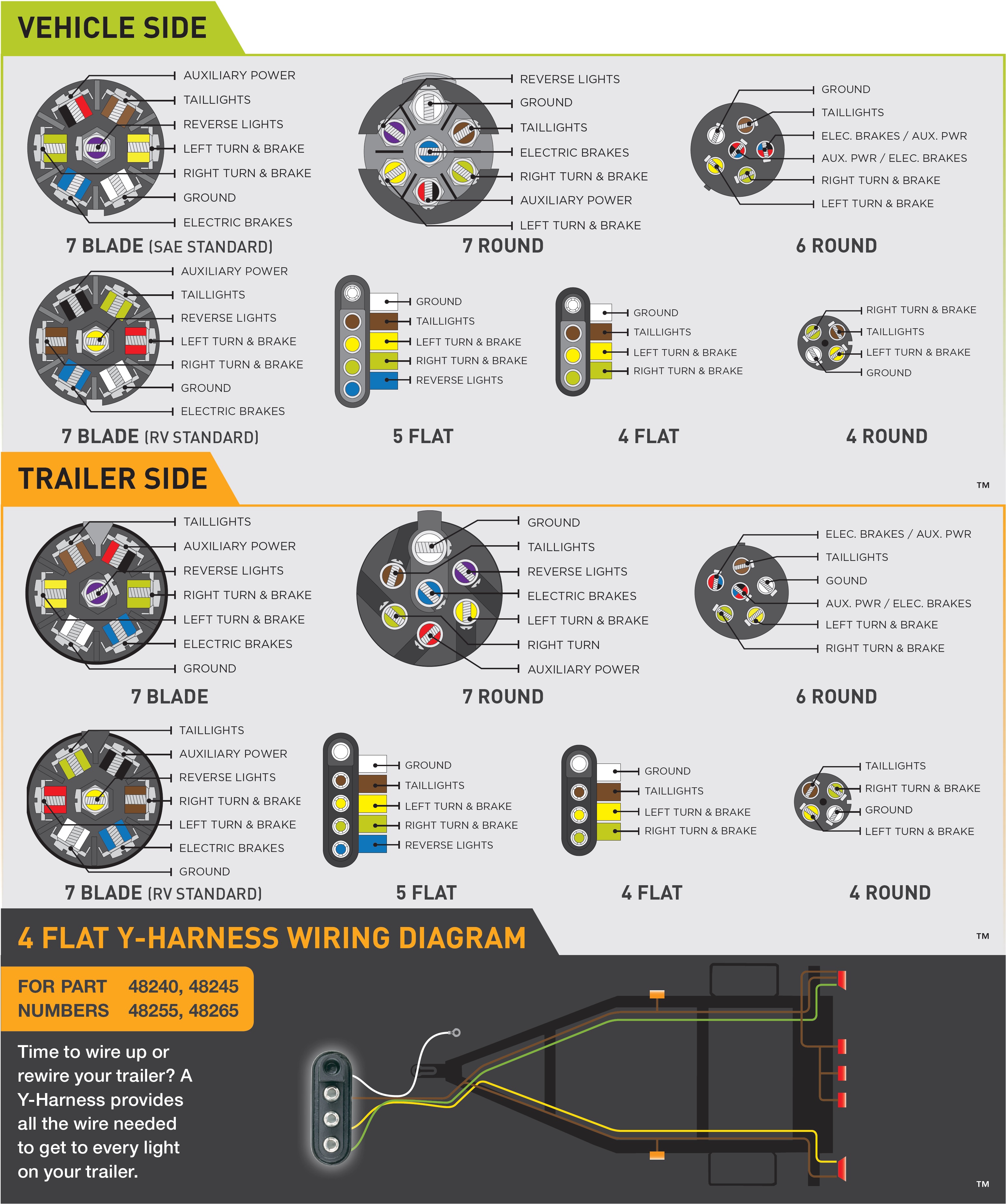
The trailer wiring diagrams listed below should help identify any wiring issues you may have with your trailer. This trailer breakaway wiring diagram version is more appropriate for sophisticated trailers and rvs. These additional wires allow a for trailer brake controller to be installed and a connection between the vehicles power supply and a 12 volt battery for a breakaway kit or an additional auxiliary power source. Connect other blue wire of break away switch to the blue wire labeled brake from the break away box b. Some trailer builders just connect this wire to the frame then connect the ground from all the other lights and accessories to the frame as well. Blue wires are interchangeable on the break away switch 3.
Various connectors are available from four to seven pins that allow for the transfer of power for the lighting as well as auxiliary functions such as an electric trailer brake controller backup lights or a 12v power supply for a winch or interior trailer lights. Trailer breakaway kits are designed to bring trailers safely to a stop by activating the electric brakes should a trailer disconnect from the tow vehicle during transit. It may transfer power better hence the connector is suggested for higher level electric in the car. If necessary extend the wire from the trailer breakaway switch with 14 gauge automotive primary wire and solderless connectors. The trailer wiring diagram shows this wire going to all the lights and brakes. It reveals the parts of the circuit as streamlined forms as well as the power and signal connections in between the gadgets.
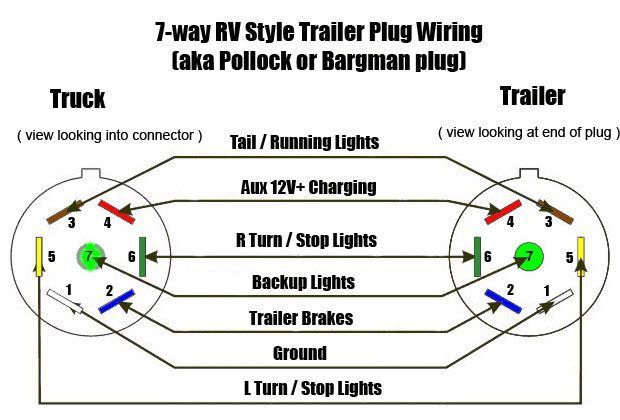
A wiring diagram is a simplified conventional photographic depiction of an electric circuit. Ideally the safety chains will prevent a trailer from disconnecting if the coupler comes off the ball. Here is the diagram for 7 pin connector. White pin for the ground. This guide will be discussing trailer breakaway box wiring. Splice one blue wire of the break away switch to the electric brake wire coming from the trailer side connector a see diagram on next page.
Assortment of electric trailer brake wiring schematic. Trailer wiring diagrams trailer wiring connectors. Variety of trailer breakaway wiring schematic.
Gallery of Trailer Breakaway Wiring Diagram