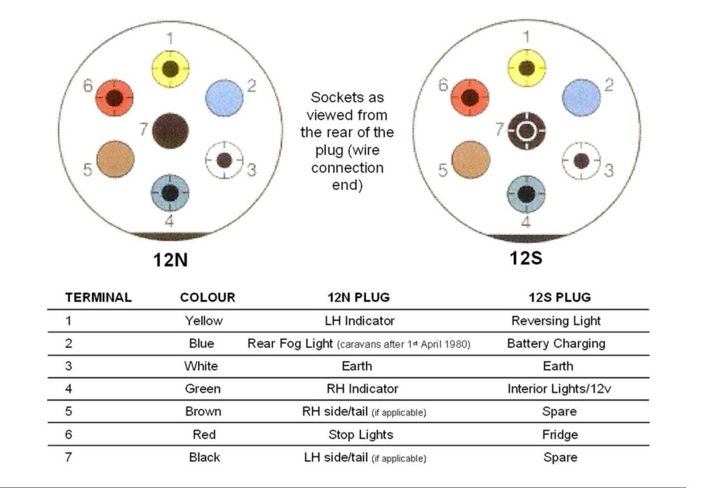
You can use this socket with uk 7 pin plugs which are on all uk trailers and caravans but you need to use a converter which will split the 13 pin electrics down to two 7 pin sockets or one 7 pin socket depending on what you are towing. This wiring diagram for trailer plug in ireland version is far more acceptable for sophisticated trailers and rvs.
124aba1 1978 Holiday Rambler 50 Amp Rv Plug Wiring Diagram
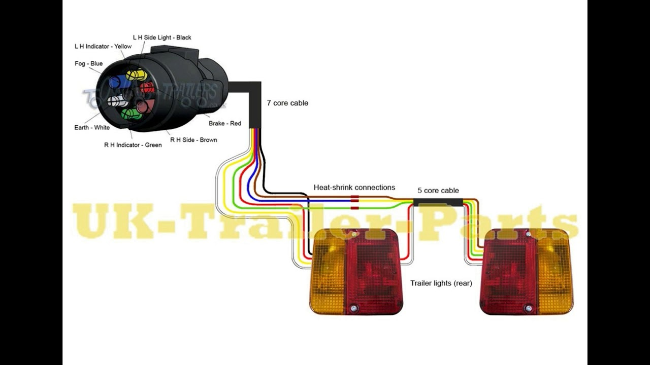
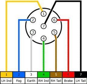
Trailer plug wiring diagram ireland. Apr 8 2019 explore johnny js board trailer wiring diagram on pinterest. 7 way plug wiring diagram standard wiring post purpose wire color tm park light green battery feed black rt right turnbrake light brown lt left turnbrake light red s trailer electric brakes blue gd ground white a accessory yellow this is the most common standard wiring scheme for rv plugs and the one used by major auto manufacturers today. 1 4 wire the first 4 pins white brown yellow green just like the 4 pin connector above. The trailer wiring diagrams listed below should help identify any wiring issues you may have with your trailer. It will also become standard in the uk and ireland over the next couple of years on new trailers caravans etc. Wiring diagram for 7 pin trailer plug wiring diagram 7 pin trailer plug ford wiring diagram for 7 pin flat trailer plug wiring diagram for 7 pin round trailer plug folks comprehend that trailer is a car comprised of quite complicated mechanics.
Trailer wiring diagrams trailer wiring connectors. Here is the diagram for 7 pin connector. When wiring a trailer connector it is best to wire by function as wire colors can vary. This vehicle is designed not only to travel 1 place to another but also to take heavy loads. Trailer connector wireing diagram. See more ideas about trailer wiring diagram trailer utility trailer.
Traditional trailer with brakes use a 5 pin connector. This type of connector is normally found on utvs atvs and trailers that do not have their own braking system. 4 pin trailer wiring diagram. Blue electric brakes or hydraulic reverse disable see blue wire notes below in the trailer wiring diagram and connector application chart below use the first 5 pins and ignore the rest. It may transfer electricity better therefore the connector is suggested for higher level electric in the vehicle. Below is the generic schematic of how the wiring goes.
We have an excellent wiring diagram on our website i will provide you a link so you can look at it. Need to know which color wire go to which post. Above we have describes the main types of trailer wiring diagrams. Various connectors are available from four to seven pins that allow for the transfer of power for the lighting as well as auxiliary functions such as an electric trailer brake controller backup lights or a 12v power supply for a winch or interior trailer lights. This report will be talking wiring diagram for 7. Note that this type of 4 pin connector is less common that 4 pin flat connector.
Various styles of connectors are available with four to seven pins to allow transfer of power for the lighting as well as auxiliary functions such as electric trailer brake control backup lights etc. White pin for the ground.
Gallery of Trailer Plug Wiring Diagram Ireland